

Clamping Support (PartDesign, SheetMetal & TechDraw)


This tutorial explains how to model a clamping support for pole mount antenna in FreeCAD 0.19. Through this example, we will see how to design a basic sheet metal product with PartDesign and SheetMetal Worbenches (WB). Then how to made a drawing of unfolded sheet metal with TechDraw WB.
-
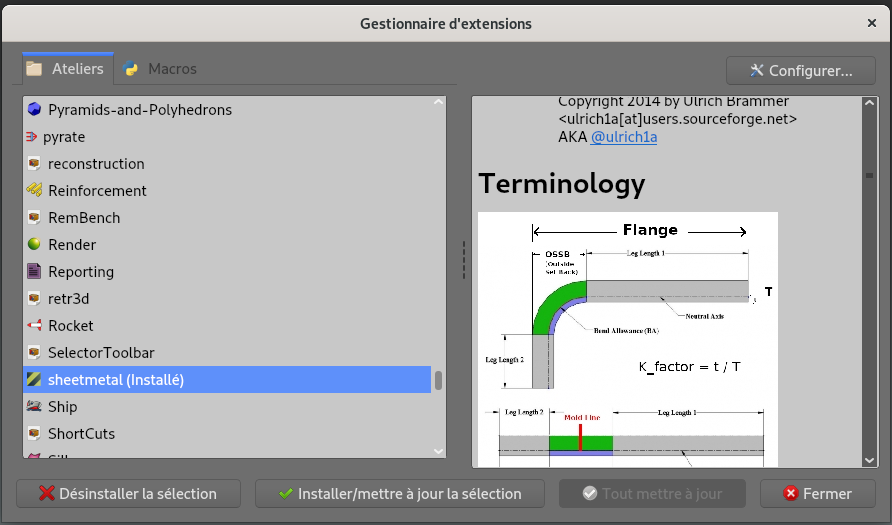
Step 1: Install SheetMetal WB (optional)
(optional - if you have not yet installed SheetMetal WB)
1) Go to -> Tools,
2) -> Addon Manager,
3) Select sheetmetal from the drop-down list,
4) Click on Install/Update.
-
Step 2: Made a first extrusion
1) Go to Part Design WB ;

2) Create a new Sketch on XY plane in Part Design ;

3) In Sketcher WB, reproduce the sketch below : first, use Rectangle and Slot functions to made the shape, then add constraint ;
NB : To add a cotation between the two arches of a Slot you can use construction lines tangent to the arches.
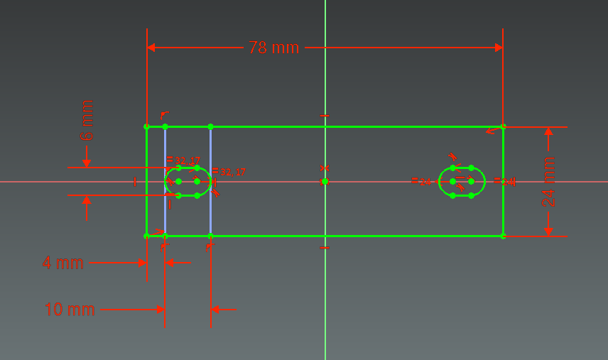
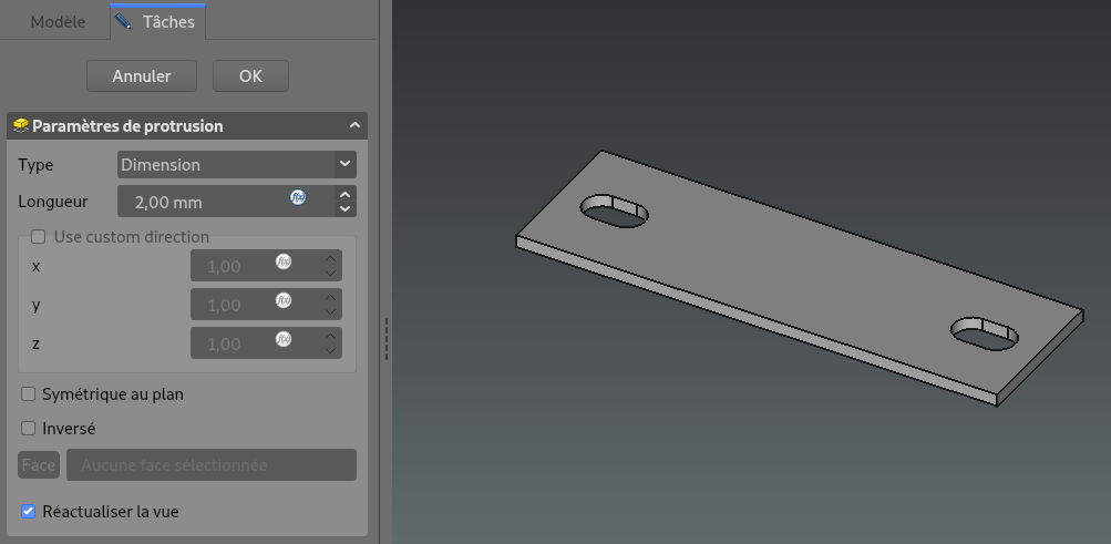
4) Extrud a solid form the created sketch with Pad function ;

5) Sheet metal thickness is 2 mm as showed below.
-
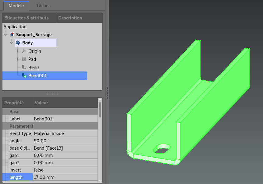
Step 3: Add Bends
1) Go to Sheet Metal WB ;

2) Select a edge of the previously created Pad and create a bend with Make Wall function ;

3) Set parameters :
- angle to 90,00°,
- Bend Type to "Material Inside"
- lenght to 17,00 mm.
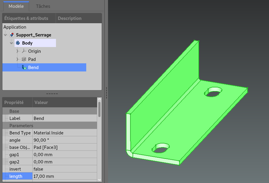
4) Select the opposite edge and made same bend with same parameters.
-
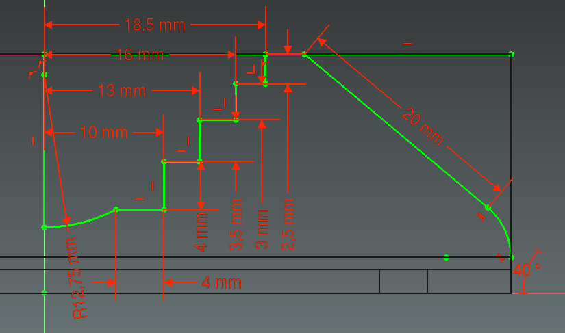
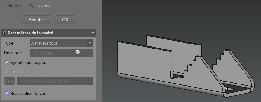
Step 4: Draw Pocket shape
1) Create a new sketch on XZ plane ;
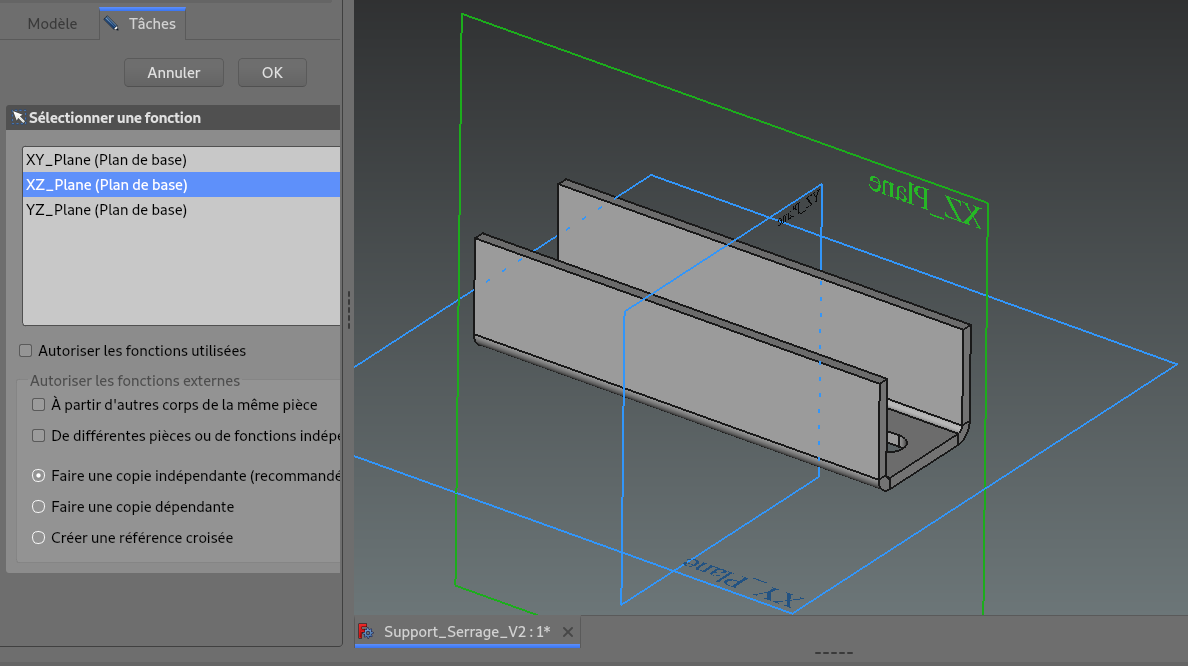
2) Reproduce the sketch : below at the side of the part,
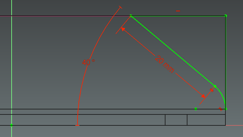
3) Then on the inside of the part.
-
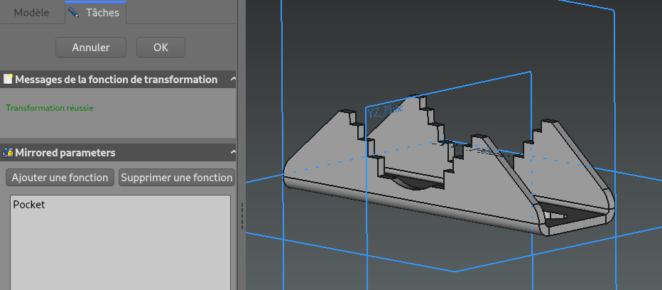
Step 5: Add symetrical Pockets through the two bends
1) Leave Sketcher and make a Pocket with step 4 sketch ;

2) Type is Through all, in order to reach the two bends.
3) Use Mirrored function to add symetrical pockets ;

4) Mirror must be executed on the YZ plane.
-
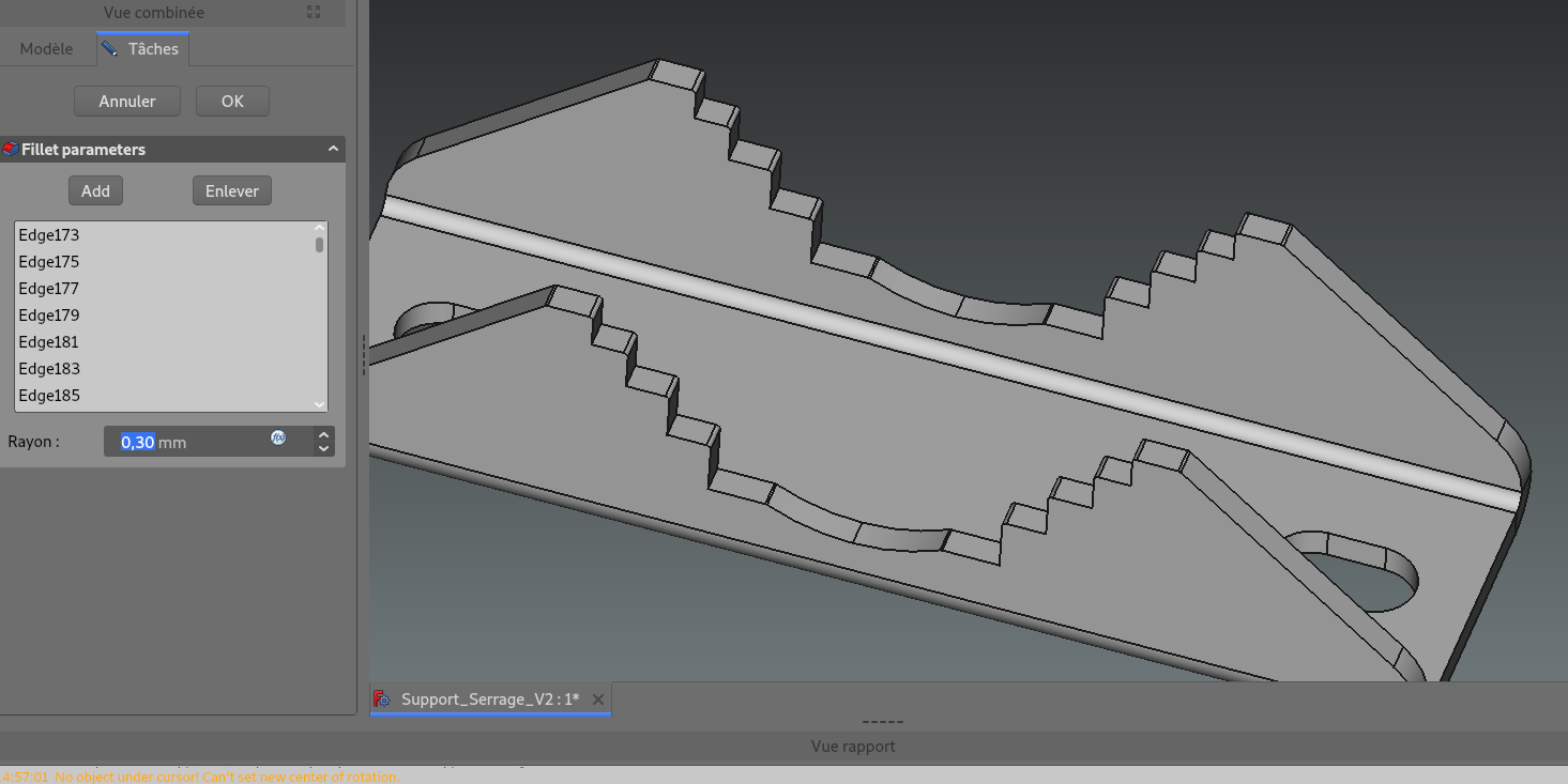
Step 6: Add Fillets (optional)
1) For more realism, you can add round edges with the Fillet function ;

2) Fillet can be set at 0.30 mm on all protruding angles.
-
Step 7: Flatten Sheet Metal
1) Once the part is finished, we will be able to unfold it by returning to the Sheet Metal WB ;
2) Select the base plane of part and click on Unfold function ;

3) You have to chose a K-factor before cliking on OK. Here ANSI.
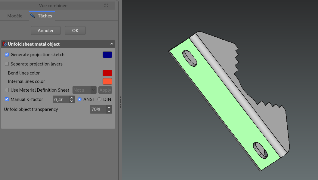
It will generate a solid and a sketch as below, that correspond to unfolded sheet metal.
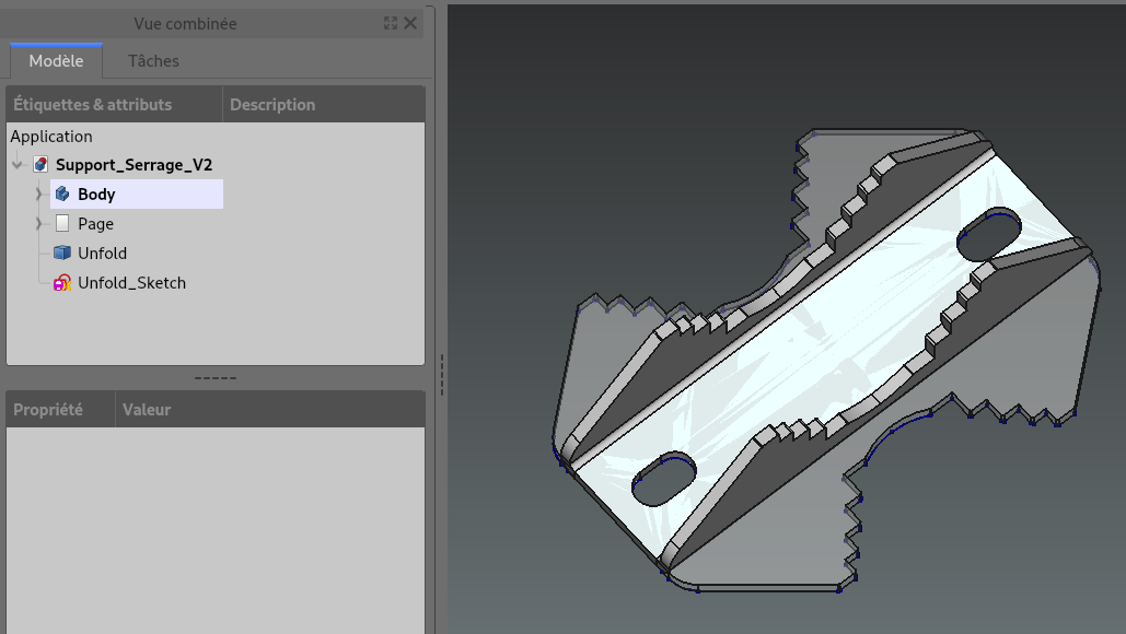
This will allow to insert an unfolded view of sheet metal with TechDraw WB :
4) Create a new Page ;
5) Select a face of Unfold body ;

6) Use Insert View function.
-
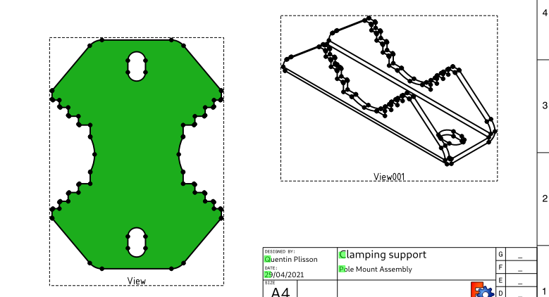
Step 8: Drawing Example
Below you can find an example of drawing for the Clamping Support with TechDraw default template.

1) Functions used to insert views : Insert View - to add five views of the part ; Insert Detail View - to insert detail A ;
2) Functions used to place dimmensions : New Horizontal ; New Vertical ; New Radius ; New Angle ;
3) Functions used to add annotation : Insert Annotation ; Add Centerline to Face - to made symmetry lines ; Add a cosmetic line - to add bending line.