Crankshaft, Flywheel Mounting Flange, Shaft, Main Bearings, and Keyway (i4 Engine)


Tutorial to construct the crankshaft, Flywheel Mounting Flange, Shaft, Main Bearings, and Keyway of a i4 Engine that will be Connected with the 4 Cylinder Pistons by using the connecting Rod Visualization and Modelling Muhammad Annawfal Rizky Sihotang 2106718281
-
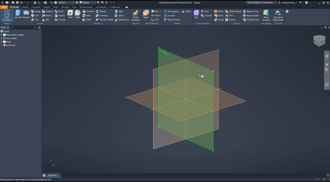
Step 1: Step 1: Start Constructing Using XY Plane
-
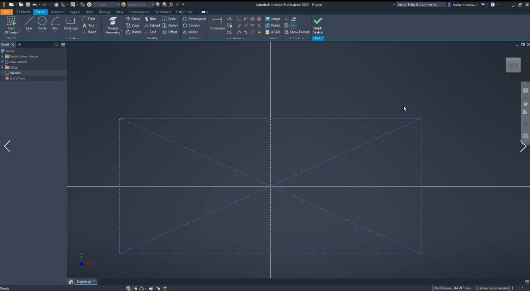
Step 2: Make Construction Rectangle
By making this rectangle construction, will be a lot more easier to find the center for the next sketch steps
-
Step 3: Sketching counterweights
Sketch a circle from the center point with 44 mm distance and 72 mm for the diameter
- Draw line on each side of the circle
- Connect the line using the arc tools
- Set the dimension at 33 mm for the line
- Set the tangent at 80 for the arc line
- To make the line parallel for both side and the circle, the Constraint tangent can be used
- To make the edges symmetric, the Symmetric constraint can be used
-
Step 4: Extruding Counterweights
Extrude the sketch with 15 mm thick to make the counterweights
-
Step 5: Sketching CrankPin
Sketch Circle with 72 mm diameter on the front side of the Counterweights
For the backside, Sketch a circle with a 54 mm diameter
-
Step 6: Extruding Crankpin
Extrude The Front Crankpin with 38 mm thick and the Back Crankpin with 46 mm
-
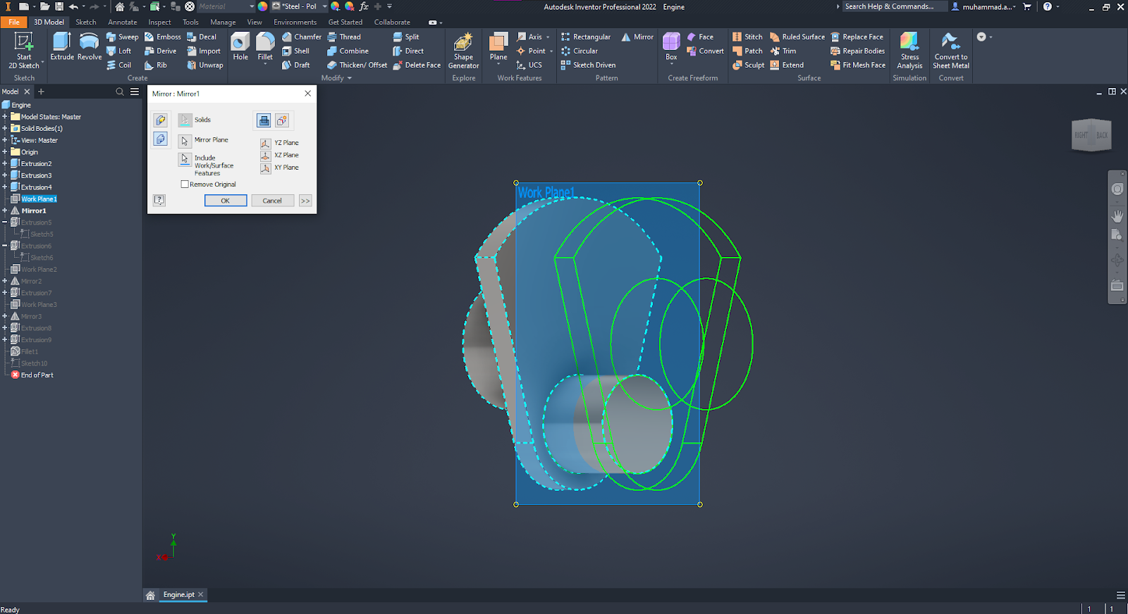
Step 7: Mirroring Counterweights
Using the Midplane between the Crankpin and the counterweight, make a new work plane
After making a new work plane Use the Mirror tool to duplicate the Counterweights
-
Step 8: Reverse Counterweight
SKETCH
Sketch the counterweights but in opposite ways from the parts before
- Sketch a circle with 72 mm diameter
- Draw a arc line with the same degree like the counterweights before
- Connect the arc line with the circle with a line that symmetric from the left and right side
EXTRUDING
- Extrude the surface with 15 mm thick
CRANKPIN
- Draw a circle with 54 mm diameter and extrude it with 46 mm thickness
- Using the midplane, mirror the reverse counterweight
- Draw the next circle on the bottom part of the counterweight with 72 mm diameter and extrude with 38 mm thick
- Ste
-
Step 9: Final Mirroring
Make a midplane for the final mirroring
Select all the parts before and use the mirror tool to duplicate and finish the crankshaft body
-
Step 10: Flywheel Mounting Flange
SKETCHING
- Draw a circle with 144 mm diameter at the left side of the crankshaft
- Draw a construction circle with 110 mm diameter
- Create a small circle with 10 mm diameter
- By using the circular pattern tool, create 8 circle around the construction circle that have been created
EXTRUDING
- Extrude the big circle with 15 mm thickness
-
Step 11: Shaft, Keyway, Main Bearings
Shaft and Main Bearings
- Start 2d sketch on the left side of the Crankshaft
- Draw a circle with 72 mm diameter
- Extrude with 38 mm Thick
Keyway
- Create a circle with 32 mm diameter in the Shaft Surface
- Extrude with 80 mm thick
-
Step 12: Fillet
Fillet all the edges, as shown in the picture below with 3 mm for the radius edges