

Dialing in a filament and specifying the Max Volumetric E(xtrusion) value

The purpose of this tutorial is to accompany a video I did for our students as to how to dial in a filament
the video is here
-
Step 1:
Load the filament and set a desired extrusion temperature
-
Step 2:
Extrude 50mm filament at a slow speed. Speed in gcode is specified in mm per minute (mm/min) so for example 120 will mean 120mm/min of 2mm/sec A good number to start of with for most filaments (Except some flexible) is 180 for flexibles I start off at 60m. if you have an interface like pronterface you can specify extrusion length and speed in the gui otherwise you have to go into which ever part of your program that allows you to send G-code to the printer if your printer runs on G-code.
First switch to relative addressing with G91
Then send
G1 E50 F180
The F parameter specifies the speed in mm/min
-
Step 3:
Inspect what extruded and increase the speed parameter by 60 and repeat the Gcode or the extrusion through the GUI
so you do
G1 E50 F240
G1 E50 F300
.... etc
-
Step 4:
each time inspect what you extrude
At some point things will change, What extrudes will either look different (shorter, fatter, pearly etc) or you will hear the extruder click
Now you know you went too fast with your extrusion - go back to the last one Lets assume for this tutorial things got different at 420 so the last good one was 360
-
Step 5:
Now calculate the volume of 1mm of your filament for 1.75mm filament this is
(1.75/2) ^2 * PI * 1 the times 1 at the end is for the 1mm height of the cylinder. For 1.75mm that value is about 2.4. So 1mm of 1.75mm diameter filament has a volume of 2.4 cubic mm (mm3 from now on)
-
Step 6:
Printers calculate in mm/sec so we got to take the last good value - 360 in our example and divide it by 60 as there are 60 seconds in a minute. we get 360/60 = 6
-
Step 7:
Multiply that number with the volume of 1mm of filament which is 6*2.4 = 14.4 and deduct about 10% to have a safety buffer and you will get 13
So for our fictional filament the max safe extrusion rate is 13 mm3/sec
-
Step 8:
If you use prusa slicer or slic3r or your slicer supports a max volumetric E field enter that value into that field and you are done with this part and go to step 10
-
Step 9:
If not you will have to calculate the max speed in mm/sec for all your moves. As the extrusion gets pressed onto the plate or the layer below it takes a form that is roughly rectangular with the dimensions of the width = layer width and the height = layer height.
Now for our example lets assume We are printing with a .8 nozzle now the layer width for the outside layer should be between 110 and 130 % nozzle width - for ease of math lets assume a layer width of 1mm and a layer height of .4 mm (best layer adhesion is at a layer height between 25 % and 50% nozzle diameter)
So 1mm of extruded perimeter will have a volume of 1 * .4 * 1 = .4 cubic mm (mm3/mm)
So the max speed for that layer would be 13/.4 = 32.5 mm/sec that we can safely extrude. Now for a small nozzle like a .4 and smaller that value will get quite high and will exceed the maximum recommended speed of the printer or the max recommended printing speed of the filament (some Nylons specify 30 or 20 or even 10mm/sec as max speed to assure good bonding) so always take the lowest of these values
-
Step 10:
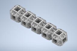
Now its time to print a test piece. We usually print Multiwall from our
https://grabcad.com/library/frc1989-filament-dial-in-1
folder.
After printing this you look at the walls the first one is 1mm the 2nd one 1.25mm the 3rd one 1.5mm and the fourth one 2mm and the one connecting the 3 is 3mm thick. Print with enough perimeters (walls) to at least get to 1.5mm or more) so we get a solid piece of plastic
-
Step 11:
Inspect the piece and measure with a caliper if you have signs of under or over extrusions establish a min and max range by changing the extrusion multiplier to get you a nice will with good layer adhesion
-
Step 12:
The measurements should give you an idea if you have an over/under print at the different thicknesses which not only shows you how your slicer and printer work together but also gives you the data you need to specify a backlash when printing gears to account for said overprint. (you should shoot for a slight overprint. You can also measure at different points of the walls and if your printer is working right there should be a difference of less than a couple thousands of an inch. (except maybe at the seam position
-
Step 13:
Now you can print either a cube or the bridge test to test that one or we usually print the file rtest (roboticstest) which has parts often used in the robot like hex holes, 1/4in clearance holes and 1 1/8 in clearance for bearings both laying down and standing up plus some bridges and pins to test stringing and a progressing overhang. The goal of the above is not necessarily to produce the nicest model but the strongest part while being accurate enough so in many cases we take a little stringing for layer adhesion.
-
Step 14:
At the end we break the piece in multiple places to get a feel for the strength. a better test is the flat piece that can be mounted in test equipment if you have it and be tested there for impact or strength.
