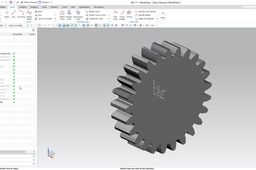
How to create spur gear in Siemens NX?

This tutorial presents the modeling of an external spur gear in Siemens NX.
The detailed modeling process is demonstrated on this video:
UPDATE: At ~ 2:40 leave the Limit options at default (At Point). See the errata video for the reason:
https://youtu.be/PUpdlyQcaOs
-
Step 1:
Copy these parameters into a text file and save it. Rename the file extension to .exp.
[degrees]alpha=20 //Reference Pressure Angle
c=sqrt(1/(cos(alpha))^2-1)/pi() //Parameter of Involute Curve
[mm]m=3.5 //Module
[degrees]phi=arctan(yc/zc)+90/z //Rotation angle
[mm]r=m*z/2 //Reference Radius
[mm]ra=r+m //Tip Radius
[mm]rb=r*cos(alpha) //Base Radius
[mm]rc=m*.38 //Tooth Blend Radius
[mm]rf=if(m>1.25)(r-1.25*m)else(r-1.4*m) //Root Radius
t=0 //NX Parameter
[mm]xt=0 //x Coordinates of Involute
yc=rb*(sin(deg(c*pi()))-cos(deg(c*pi()))*c*pi())
yt=rb*(sin(deg(t*pi()))-cos(deg(t*pi()))*t*pi()) //y Coordinates of Involute
(Integer) z=25 //Number of Teeth
zc=rb*(cos(deg(c*pi()))+sin(deg(c*pi()))*c*pi())
zt=rb*(cos(deg(t*pi()))+sin(deg(t*pi()))*t*pi()) //z Coordinates of Involute -
Step 2:
Launch NX, create a new model file, push the CTRL+E keys and imports the expressions.

-
Step 3:
Create the involute curve by Law Curve command.

-
Step 4:
Create a circular pattern on the involute curve.

-
Step 5:
Draw a line which starts from the end point of involute and tangents the curve. Set its limit by equation.

-
Step 6:
Launch the Join Curve command and join the line and the involute curve.
-
Step 7:
Draw the tip and root circles by full circle. Draw a tangent circle for the tooth blend.

-
Step 8:
Trim the unnecessary parts of the curves.

-
Step 9:
Mirror the involute curve and the tangent circle.

-
Step 10:
Trim the tip and root circles.

-
Step 11:
Create a circular pattern, set the parameters.

-
Step 12:
Extrude the curves to get the spur gear body.


