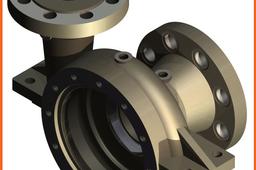
How to model a Centrifugal Pump Body (Spiral construction) using Inventor 2014?

We have to abide by all the conditions from the technical drawing
Note: You can watch my live tutorial for modeling this part here: https://youtu.be/yxEAv2p31zw
-
Step 1:
1. New work plane at 45° from XZ Plane around the Y Axis (see 1, 2, 3, 4 steps)

-
Step 2:
2. New sketch: Circle Ø26.75 with center at 123.5 on the same vertical with the origin (Center Point)

-
Step 3:
3. Coil tool with Spiral option (Pitch=28, Revolution=7/8)

-
Step 4:
4. Result from Coil/Spiral applying

-
Step 5:
5. Creating of 5 sketches (5 circles), where the last 4 of them are related to the Center point only

-
Step 6:
6. Loft tool on 5 sketches, using the spiral curve on the spiral feature as Centerline

-
Step 7:
7. Result from Loft tool applying

-
Step 8:
8. Revolving half circle on S1 around its diameter on 180° to create a hemisphere

-
Step 9:
9. Extrude tool on a circle (radius=123.5) in the Center point using a 24 simmetrical distance

-
Step 10:
10. Move Bodies tool to move the (unique) solid 200 to the back

-
Step 11:
11. New 5 similar sketches (only one dimension differs), related to the same Center point as above

-
Step 12:
12. Changing color of the Solid1 using Right click/Properties

-
Step 13:
13. Loft tool with New solid option, on the 5 sketches with Centerline from the spiral curve

-
Step 14:
14. The result is another solid in the same .ipt file (or two solids of different colors)

-
Step 15:
15. New sketch on an existing plane - a circle is automatically projected (like in 005 or 008 picture)

-
Step 16:
16. New work plane parallel with XZ Plane through the circle center (see 1, 2, 3 steps)

-
Step 17:
17. New sketch on XZ Plane - a centerline from the projected circle center, and other 3 lines

-
Step 18:
18. Revolving the closed loop to obtain a conic feature associated with the Solid1

-
Step 19:
19. New sketch for the Solid2 with a line projected from the circle of the Solid1

-
Step 20:
20. The sketch also related to the Center point will be revolved - attached to the Solid2

-
Step 21:
21. A sketch created on the sloped plane is revolved between it and the next one, to fill the gap

-
Step 22:
22. Filling the central hole of the Solid2

-
Step 23:
23. New sketch with a circle of Ø310 in a new work plane at -65 from the XZ Plane

-
Step 24:
24. Extruding the circle To next with a taper of 3°, as in the above part drawing

-
Step 25:
25. A new sketch in the plane XZ to extrude simmetrically on 120

-
Step 26:
26. The result of the last two extrudes

-
Step 27:
27. Move Bodies tool on Y Offset = 200 to get back the Solid1

-
Step 28:
28. Combine tool to subtract (Cut) the Solid1 (as Base) from Solid2 (as Toolbody)

-
Step 29:
29. The result (intentionally sectioned)

-
Step 30:
30. A new sketch for creating the revolved external body

-
Step 31:
31. Result of Revolution

-
Step 32:
32. A new sketch for creating the revolved internal body

-
Step 33:
33. The result (intentionally sectioned)

-
Step 34:
34. New sketch with a Ø34 circle to create a boss for a G1/2" hole

-
Step 35:
35. The ISO Pipe G1/2" hole, through but not through all

-
Step 36:
36. Rib tool to create a rib, starting from a sketch in XZ Plane with a sloped line at 30°

-
Step 37:
37. Final part


