

HOW TO USE BOTH FLOW SIMULATION AND THERMAL ANALISIS IN A HEAT EXCHANGER

Heat exchanger
-
Step 1:
Create simplify heat exchanger by this drawing

-
Step 2:
In SW you get model. Turn on “Flow Simulation” module

-
Step 3:
Create new flow project

-
Step 4:
On “type of task” page turn on “heat conduction in solids”

-
Step 5:
On page “fluid” and add “water”

-
Step 6:
On page “material” add material aluminum. All other parameters are default

-
Step 7:
Create plugs in holes of detail

-
Step 8:
Create boundary conditions on detail holes.
Create a parameter of the mass flow 5kg/s at the entrance to casing. Temperature is 573K
-
Step 9:
At the out of casing, create a boundary condition "ambient pressure"

-
Step 10:
At the entrance to tube create a boundary condition "incoming speed" 1m/s and temperature is 278K

-
Step 11:
At the outlet of the pipe, set the boundary condition "coming out speed" 1m/s

-
Step 12:
start the calculation

-
Step 13:
After calculations add results "trajectory of the flow" – flow temperature, type – tubes, faces of the inner pipe (incoming, exiting), number of points - 100

-
Step 14:
add results "trajectory of the flow" – flow temperature, type – tubes, faces of the inner pipe (incoming, exiting), number of points – 20

-
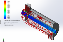
Step 15:
You get result!!
Temperature rises by approximately to 30 degrees.
I do not know the parameters of your heat exchanger, so the results are approximate. This is just an example, based on it, you can make similar calculations.
