

How to Use the Stratasys Packaging Design Application to Create a Packaging Prototype

In this tutorial, we will show you how we used a J55 printer and our new packaging design application to create a product prototype with its packaging -- all in one print. That’s right! We printed a product prototype together with its packaging in one print, eliminating the need for additional resources for laser cutting, vacuum forming, etc.
3D printing with PolyJet enables us to include within the package design straight thin walls, full color graphics, fine features, transparency and high-resolution text and logo's.
-
Step 1: Introduction to Package Design
The PolyJet J Series offers a new solution for the consumer goods and electronics design market: the ability to create in-house full CMF models not only for the product themselves but their packaging as well – in one solution. This new ability can save significant time and money.
By using this new application, you can simulate high-precision, high-quality, thin-walled cardboard packaging with all textures and graphics applied.
In a time where packaging is one of the most important drivers for purchase, and the experience of unboxing is critical for customers, (starting from the packaging itself), manufacturers and designers need to step up their game when it comes to product design, including packaging.
According to the research, almost a third of product purchase decisions are based on the product’s packaging. In addition, roughly two thirds of consumers said they have tried a new product because of its packaging.
Clearly, package design now goes hand in hand with product design, and 3D printing lets you develop both at once from an early stage in the design process. And now, fine-tuning of all parts can be done via 3D-printing and in-house.
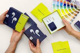
One example is this packaging prototype we developed here at Stratasys:

This earbuds packaging model was entirely created on one tray, using the J55. The packaging includes:
- A sleeve for user manual
- Earbuds case
- The earbuds themselves
- Charging case
- An inner part representing vacuum forming
- Full color packaging with a clear window
Creating both the product and the packaging completely in-house allows for:
- Endless design iterations
- Testing UX with potential clients for the unpacking experience
- Fast production of fantastic models with fine details
- Facilitated communication between designers and management for better decision making
- Decision making earlier in the process, achieving better design in short schedule.
In addition, by using a singular technology throughout the whole design process, you’ll save time contacting different suppliers.

Earbud packaging including wireless earbuds and all accessories inside.

Thin accurate walls with the exact tolerance needed between parts.

Fine features with color.


Transparent parts can be printed either together with full color parts or separately for easy post-processing. In this case, we printed the clear window as a separate part in order to polish it easily from all sides for a super glossy finish. Transparent windows like this are great for giving consumers a sneak peek at the product.

Part simulating vacuum formed insert. Designed to securely hold earbuds, earbud case, and charging cable.

Perforated sleeve for user manual. Simulating laser cutting.
Below, we’ll show you how to make a packaging model like this on a Stratasys PolyJet J55 printer in a single print.

-
Step 2: How to prepare the files for print in your CAD Program
Each packaging has different design elements, and you can get improved results by planning ahead and making a few adjustments that will get you an improved surface finish and easier post processing.
For this specific model, we made a few adjustments to optimize appearance and functionality:
a. Adding a sacrificial shell to the outer box.
The outer box was designed with the earbuds extruding 1 mm from the surface. We decided to print the outer box vertically, so the inside of the box will be printed without any support, and we can have a glossy finish inside.
In this orientation there was supposed to be support material under the earbuds extrusion as it's our print software’s default to print support material under overhanging / unsupported regions.
To avoid inconsistent surface finish on the front of the box and preserve a uniform surface finish, we added a sacrificial shell to the entire outer wall that we could remove and discard for easier post-processing.

Sacrificial shells can be useful if, for example:
- You plan to add displacement to your model
- You want a completely glossy part
- The geometry of your part would require lengthy support removal
- Your model includes long, enclosed sections that would otherwise be filled with support material
- Your model includes tall and thin walls with detailed features that have gaps between the features
- You are printing flat, clear parts that have high surface finish requirements (reduces chances of curling and layer lines, improves overall print quality).
We used a tolerance of 0.3 mm between the sacrificial shell and the outer box. A tolerance lower than that might result in the two parts sticking together.

b. Making a tolerance between glossy parts
If you are printing in glossy surface finish, make sure to have a minimal tolerance that allows for parts to be assembled together. For example, we printed the earbuds themselves and vacuum forming both in glossy so that the earbuds would fit better into the vacuum formed parts using a tolerance of 0.2 mm.
-
Step 3: Save parts in the optimal way for printing
Save files in a 3D-compatible file format. Here is a list of design and CAD files currently compatible and editable from within GrabCAD Print.
Parts containing more than one shell and needs to be printed together should be saved as one part from the native CAD.
-
Step 4: Add textures and graphics to selected parts of the model
We applied an image texture to the outer box only. We did this using UV mapping in an external design program called Blender.
a. Import OBJ to Blender

b. Unwrap the model: You’ll need to create a 2D representation of the 3D model in order to apply the texture map. To do this, Mark seams (the edges where the model is "cut open") for unwrapping, and select unwrap in order to create the UV map.

c. In the UV Editor open the graphics and align the UVs' to match the graphics


The UV map is divided to 3 areas:
- Outer graphics
- Inner surfaces: plain white
- Lip: a color matching the graphics.
d. Export as an OBJ file.
e. Repeat the same process for any other parts with graphics.
-
Step 5: Prepare the print tray
If color and material designations were not applied in the previous step, consider which elements of your project should be imported as an assembly and printed as a single part to reduce the need for extensive assembly and post processing later. In our example the earbuds themselves are comprised of multiple bodies that can have different color assignments.
a. Open GrabCAD Print and import all parts.
b. Define the materials for the print tray.
We printed this model on J55 printer; it has 5 material channels so we could achieve the best color with CMYKW or great color with transparency with CMYWT.
We did not load black in the printer since we wanted to use the clear material on the same tray. You can see the model contains dark colors which we were able to print with four color profile without black (CMYWT).
Material loaded on the printer below:

c. Select the desired colors for each part. We selected the Pantone™ colors directly from within GrabCAD Print. You can also input values in RGB or HEX, or select a pre-set color from our Digital Materials menu.
You can also print transparent parts with VeroClear (like the window pictured below), or print transparent colors by using the color picker and color slider to find a color you want.

d. Select part orientation for each part of your assembly.

In our case for the outer box, the open end of the larger side was printed standing up so it wouldn’t fill up with support material.
In addition, we printed the inner small part of the outer box upside down in order to get a glossy finish for easier post process.
When choosing an orientation use your own priorities as a guide. Take into account the finish you would like to reach and post prosses for each part.
Note: Packages can be printed on any J -Series printer. In this case, we printed on the J55.
e. Select material finish that optimizes each part of the assembly. For example, a glossy finish gives your part more strength and sharper color, helps it withstand distortion, and saves time and money on support removal and post-processing. Graphics will be optimized if printed in glossy and printed in Z axis (vertically).
f. Printing mode selection: If working on the J55, mode is set as high quality. If working on a different J -Series printer, you can choose between several printing modes to reach the quality you're looking for.
-
Step 6: Post processing
Post-processing can achieve different finishes for your models according to your design intent:
- Super glossy surface finish with additional post-processing
- A uniform glossy or matte surface finish with sand blasting or polishing
- A high level of transparency with photobleaching
In this model we achieved a uniform matte surface finish for many parts using sand blasting, a super glossy clear window with a polishing process, and a combination of matte and glossy in the outer box using both processes together.
Tip: Storing the big parts of the packaging model is recommended in the orientation it was printed in order to preserve the shape optimally.
-
Step 7: In summary
The new Stratasys packaging design application makes creating product prototypes with its packaging, ALL in ONE print -- easy!
You'll have:
- Minimal wall thickness.
- Control of tolerance between parts.
- Save significant time and money.
- Be able to simulate high-precision, high-quality, thin-walled cardboard packaging with all textures and graphics applied.
It also eliminates the need for additional resources for laser cutting, vacuum forming, etc. Now, you can develop packaging from an early stage in the design process, with more time for fine-tuning of all parts and achieve better design .
