

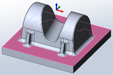
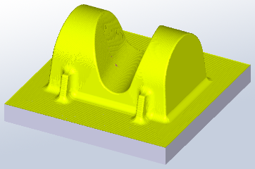
HSMWorks tutorial №2 - High-speed 3D machining


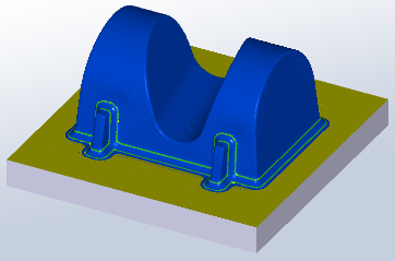
In this tutorial you will learn how to machine the part above on a high speed machine tool through the following steps:
▸Creating a Tool Library
▸Roughing: Adaptive Clearing
▸Rest Roughing: Pocket
▸Contour Machining
▸Scallop Machining
▸Scallop
▸Horizontal
▸Pencil Milling
▸Collapsed Pencil
▸Post Processing
Before proceeding, open the part Tutorial2.SLDPRT into HSMWorks.
The files used in this manual can be found in the examples folder in the folder where HSMWorks is installed. Typically, this is something like C:\Program Files\HSMWorks\examples\
𝐃𝐢𝐬𝐜𝐥𝐚𝐢𝐦𝐞𝐫: This tutorial is a representation of the original Help tutorial with the HSMWorks software suite.
This guide is intended for educational purposes and to make the features and tools of HSMWorks more accessible to the general public.
More information about purchasing, installing, and using HSMWorks can be found on the official website: https://www.autodesk.com/products/hsmworks
-
Step 1: Creating a Tool Library
In this tutorial, we will start of by creating a tool library containing all the tools we will be using first.
First, open the tool library:
➝ Choose Tool Library from the CAM toolbar or the CAM menu.
The tool library allows you to select from existing tools in a library as well as define new tools. Tool definitions can be saved in a library or just for the part you work on.
Next, create a new library called Tutorial2:
➝ In the tool library dialog, select My Libraries
➝ Click New Library
➝ Name the new library Tutorial2. Press Enter to accept the new name
This creates a new library file in My Libraries subfolder of your My Documents folder.
You can locate the library file by right-clicking on the library and pressing Open in Windows Explorer.
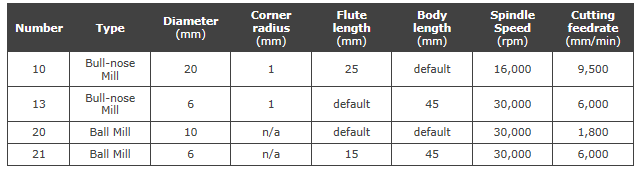
Now, add each of the following tools by pressing New Mill Tool, and then changing the type and the parameters specified below. All other parameters should be left at their defaults.
When you are done setting up the tools, press OK to return to HSMWorks. The library will be saved automatically.
-
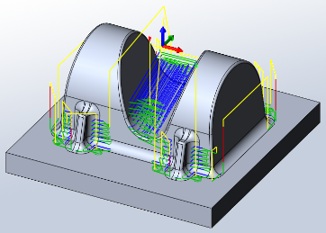
Step 2: Roughing: Adaptive Clearing
For roughing the part, we will first use an adaptive clearing strategy to remove the majority of the excess material.
➝ Click the strategy Adaptive Clearing on the CAM toolbar. This opens the Property Manager and you will see the following groups.
1. Tool
➝ Press Library
➝ From the library Tutorial2 that we created before, select tool #10 - Ø20R1mm bullnose
➝ Press Select
2. Geometry
By default, the Adaptive Clearing strategy will remove all possible material from the stock and to the model.
By default the stock is a rectangular box slightly larger than the part, and the model is set to be the solid body in the part. Both stock and model are defined in the Job which is added automatically.
The geometry tab allows you to override the default model and confinement settings, as well as the tool orientation.
In this example the default stock, model and tool orientation will work and we do not need to change anything.
3. Heights
The default heights are set to relate to the geometry such that the entire depth of the part is machined.
In this operation we will only machine down to the flat area of the part, omitting the rectangular base of the part.
➝ For Bottom choose From Selection.
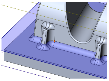
➝ For the Bottom Reference select one of the vertices along the bottom face:
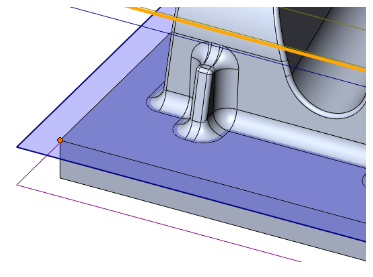
4. Passes
Adaptive Clearing
➝ Change Maximum Roughing Stepdown: 25mm
➝ Change Fine Stepdown: 2.5mm (automatically updated)
➝ Enable Machine Shallow Areas
➝ Change Maximum Shallow Stepover: 1mm
➝ Enable Flat Area Detection
Stock to Leave
➝ Set Radial (Wall) Stock To Leave: 0.3mm
Note that the axial stock to leave is automatically updated to reflect the radial stock to leave.
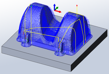
5. Start calculation
Click ✓ at the top of the property manager. This will start generation of the toolpath.
Whenever a toolpath is being generated, you can continue to work by pressing the Hide button on the Task Manager dialog.
When the Task Manager is hidden, toolpath calculation will continue in the background, and you can see progress directly in the operation manager.
Note also that for most of the strategies, it is possible to see a preview of the toolpath as it's being generated. This can be valuable to help you see early on if something is wrong so you can abort the task and go back and change the parameters.
You can bring the dialog back by selecting Task Manager from the CAM toolbar or menu.
You can either abort a task by pressing the Abort button in the task manager, or by choosing Abort Generation when right-clicking on the operation in the operation manager.
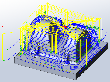
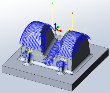
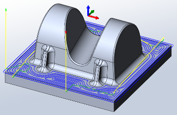
When the toolpath generation is complete, the resulting toolpath should look like this:
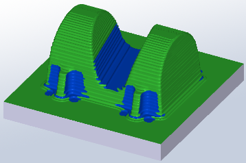
6. Verification
To verify the toolpath use the stock simulation, right click on the Job node in the Operation Manager and select Stock Simulation (All). Press the Start button and watch the stock simulation up to the final stock shape.
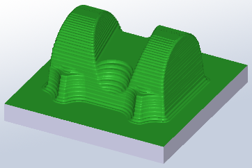
Click ✓ to exit the Stock Simulation.
-
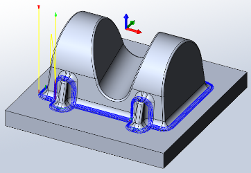
Step 3: Rest Roughing: Pocket
There are some areas where the 20mm tool did not fit. We will remove more of the remaining material there with a pocket rest milling operation.
➝ Click the strategy Pocket Clearing on the CAM toolbar. This opens the Property Manager and you will see the following groups.
1. Tool
➝ Select tool #13 - Ø6R1mm bullnose from the Tutorial2 library.
2. Geometry
Rest Machining
We only want to remove the material the previous operation did not remove.
➝ Enable Rest Machining
3. Passes
Pocket Clearing
Use these settings:
➝ Set Corner Deviation: 1.0mm
➝ Set Maximum Roughing Stepdown: 2.0mm
Stock to Leave
We use the same settings as in the previous operation Adaptive1.
➝ Set Radial (Wall) Stock To Leave: 0.3mm
4. Linking
For this tutorial, we use the Shortest Path retraction policy. This gives the shortest possible rapid movement paths, but can only be used on high speed enabled machines where rapid motion is interpolated as linear moves. Should you wish to machine the tutorial part on your machine, you may have to change this setting to suit your machine and control.
5. Start calculation
Click ✓ at the top of the property manager. The resulting toolpath should look like this:
6. Verification
To verify the toolpath use the stock simulation, right click on the Job node in the Operation Manager and select Stock Simulation (All). Press the Start button and watch the stock simulation up to the final stock shape.
Click ✓ to exit the Stock Simulation.
-
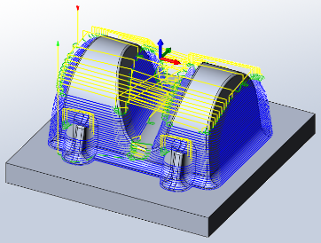
Step 4: Contour Machining
We now have between 0.2mm and 0.4mm material left on the part (0.3mm stock to leave plus/minus 0.1mm tolerance). We will use several semi-finish operations to reduce this material. In the following part of the tutorial you will learn how to set up these toolpaths.
We will create a contour operation to handle the steep areas of the part.
➝ Click the strategy Contour on the CAM toolbar. This opens the Property Manager and you will see the following groups.
1. Tool
➝ Select tool #20 - Ø10mm ball from the Tutorial2 library.
2. Geometry
Machining Boundary
➝ Select Tool Center on Boundary from the Tool Containment drop down.
We want to confine the machining to steep areas with this operation. This can be achieved by limiting the Slope range.
Slope
➝ Enable Slope
➝ Change From Slope Angle: 60deg
➝ Change To Slope Angle: 90deg
All other settings remain default.
3. Passes
Contour
Use these settings:
➝ Set Tolerance: 0.02mm
➝ Set Maximum Stepdown: 1mm
➝ Enable Order By Depth
Stock to Leave
➝ Enable Stock To Leave
We can use the default values of 0.1mm for this operation.
4. Linking
Linking
➝ Select Minimum Retraction as the Retraction Policy
➝ Change Maximum Stay-Down Distance: 10mm
All other settings remain default.
Leads & Transitions
Use these settings:
➝ Change Ramping Angle (deg): 10deg
5. Start calculation
Click ✓ at the top of the property manager. The resulting toolpath should look like this:
6. Verification
To verify the toolpath use the stock simulation, right click on the Job node in the Operation Manager and select Stock Simulation (All). Press the Start button and watch the stock simulation up to the final stock shape.
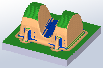
Click ✓ to exit the Stock Simulation.
-
Step 5: Scallop Machining
Next we will create a constant scallop toolpath on the shallow areas of the boss.
➝ Click the strategy Scallop on the CAM toolbar. This opens the Property Manager and you will see the following groups.
1. Tool
The previous tool #20 - Ø10mm ball should still be selected. We will leave all settings in this group unchanged.
2. Geometry
Confinement
We want to confine the machining to shallow areas with this operation. This can be achieved by limiting the Slope range.
➝ Enable Slope
➝ Change From Slope Angle: 0deg
➝ Change To Slope Angle: 65deg
Machining from 0 degrees (horizontal) to 65 degrees from horizontal ensures that there is no excess material in the transition zone between this operation and the previous operation on steep areas, and that the tool starts in areas that are already machined.
Check Surfaces
The set slope angle will also include the flat face at the bottom of the part, but we finish this later with 0 stock to leave using a horizontal finishing strategy.
To avoid machining the flat bottom of the part we can select it as a check surface:
➝ Enable Check Surfaces
➝ In the Check surface selection field, select the flat face at the bottom of the part:
3. Passes
Scallop
Use these settings:
➝ Set Tolerance: 0.02mm
➝ Set Stepover: 1mm
Stock to Leave
➝ Enable Stock To Leave
Again, we can use the default values of 0.1mm.
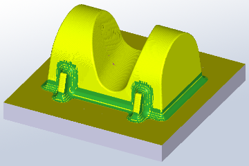
4. Start calculation
Click ✔ at the top of the property manager. The resulting toolpath will look like this:
5. Verification
To verify the toolpath use the stock simulation, right click on the Job node in the Operation Manager and select Stock Simulation (All). Press the Start button and watch the stock simulation up to the final stock shape.
Click ✔ to exit the Stock Simulation
-
Step 6: Scallop
We now have 0.1 mm left on most of the part. There is a little more on top of the base surfaces, inside the 4 mm fillets and on the lower part of the fillet at the base surfaces. We will now finish the part in these steps.
➝ Click the strategy Scallop on the CAM toolbar. This opens the Property Manager and you will see the following groups.
1. Tool
Select tool #21 - Ø6mm ball from the library Tutorial2.
2. Geometry
In the previous operations we limited the slope range to confine machining to steep areas. In this operation we want to machine the entire part in one go to get a consistent amount of stock left.
In this operation we will only machine down to the flat area of the part, omitting the rectangular base of the part.
3. Passes
Scallop Finishing
Use these settings:
➝ Set Tolerance: 0.02mm
➝ Set Stepover: 1mm
➝ Choose Inside -> Out for the Inside/Outside option.
Stock to Leave
Use these settings:
➝ Enable Stock To Leave
➝ Set Radial (Wall) Stock To Leave: 0.05mm
➝ Set Axial (Floor) Stock To Leave: 0.05mm (updated automatically)
4. Start calculation
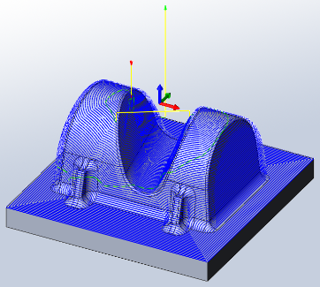
Click ✔ at the top of the property manager. The resulting toolpath will look like this:
5. Verification
To verify the toolpath use the stock simulation, right click on the Job node in the Operation Manager and select Stock Simulation (All). Press the Start button and watch the stock simulation up to the final stock shape.
Click ✔ to exit the Stock Simulation
-
Step 7: Horizontal
We will now clear the base surfaces where they are perfectly horizontal.
➝ Click the strategy Horizontal on the CAM toolbar. This opens the Property Manager and you will see the following groups.
1. Tool
Select tool #13 - Ø6R1mm bullnose from the document tool table.
2. Heights
By default, the horizontal finishing strategy will also machine across the top of the part and the small flat areas on the ridges of the part.
In this operation we are only concerned about the bottom flat face, and thus we can limit the depth range that is to be machined.
➝ For Top choose From Selection.
➝ For the Top Reference select one of the vertices above the bottom fillet:
3. Passes
Horizontal
Use these settings:
➝ Set Tolerance: 0.02mm
➝ Set Smoothing Deviation: 1mm
Stock to Leave
By default the amount of stock to leave is 0. In this operation we will machine down to the final shape of the part, without any stock allowance.
4. Start calculation
Click ✔ at the top of the property manager. The resulting toolpath will look like this:
5. Verification
To verify the toolpath use the stock simulation, right click on the Job node in the Operation Manager and select Stock Simulation (All). Press the Start button and watch the stock simulation up to the final stock shape.
Click ✔ to exit the Stock Simulation
-
Step 8: Pencil Milling
We are using a 6 mm ball mill for finishing toolpaths. The fillets between base and boss are 4mm radius. We will use parallel pencil passes to machine the fillets.
➝ Click the strategy Pencil on the CAM toolbar. This opens the Property Manager and you will see the following groups.
1. Tool
Select tool #21 - Ø6mm ball from the document tool table.
2. Passes
Pencil
Use these settings:
➝ Set Overthickness: 1.2mm
➝ Set Number Of Stepovers: 5
➝ Set Stepover: 0.3mm
Overthickness is used by HSMWorks to generate pencil passes where they would not exist for the specified tool. Here the tool radius of 3mm is smaller than the fillet radius of 4mm. With Overthickness set to 1.2mm, HSMWorks will generate the pencil passes for a larger tool radius, and uses them to guide the smaller tool into the fillets.
Stock to Leave
Use these settings:
➝ Enable Stock To Leave
➝ Set Radial (Wall) Stock To Leave: 0.05mm
➝ Set Axial (Floor) Stock To Leave: 0.05mm (updated automatically)
3. Start calculation
Click ✔ at the top of the property manager. The resulting toolpath will look like this:
4. Verification
To verify the toolpath use the stock simulation, right click on the Job node in the Operation Manager and select Stock Simulation (All). Press the Start button and watch the stock simulation up to the final stock shape.
Click ✔ to exit the Stock Simulation
-
Step 9: Collapsed Pencil
For the last finishing operation, we will use a collapsed pencil finishing toolpath over the entire part except the base surface. We can copy the previous operation, and then edit the parameters.
➝ Right-click on the last operation, Pencil1.
➝ Select Copy from the context menu.
➝ Right-click again.
➝ Select Paste from the context menu. A copied operation Copy of Pencil1 is added to the bottom of the toolpath list.
➝ Rename the copied toolpath: select and press F2. Type the new name Parallel pencil.
➝ To open the Property manager right-click Parallel pencil and select Edit from the context menu. You will see the following groups:
1. Tool
The selected tool should still be #21 - Ø6mm ball.
2. Geometry
Confinement
We will confine the toolpath to the area of the boss.
➝ In the pull down menu Machining Boundary switch from Silhouette to Selection.
➝ Disable Tangent Propagation
➝ Select an edge on the inner boundary as shown here:
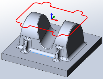
➝ Set Additional Offset: 1.0mm
3. Passes
Pencil
➝ Disable Limit Number Of Stepovers
➝ Set Stepover: 0.7mm
Stock to Leave
➝ Disable Stock To Leave
4. Start calculation
Click ✔ at the top of the property manager. The resulting toolpath will look like this:
5. Verification
To verify the toolpath use the stock simulation, right click on the Job node in the Operation Manager and select Stock Simulation (All). Press the Start button and watch the stock simulation up to the final stock shape.
Click ✔ to exit the Stock Simulation
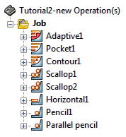
That finishes this tutorial's toolpaths; you should now have these operations in the operation manager:
-
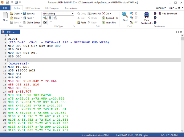
Step 10: Post Processing
We are ready to post process all toolpaths in order to make the NC-code which can be used by the machine tool.
➝ Right-click on Job in the operation manager.
➝ Select Post Process (All).
➝ Choose the desired post processor configuration, program file name and location.
➝ When you have finished editing your settings click on Post to generate the CNC program file. By default HSMWorks Edit will open and you can view and simulate the program code, and transfer it to the machine control.
Congratulations! You have completed this tutorial.