

Inserting Hardware Post-Build


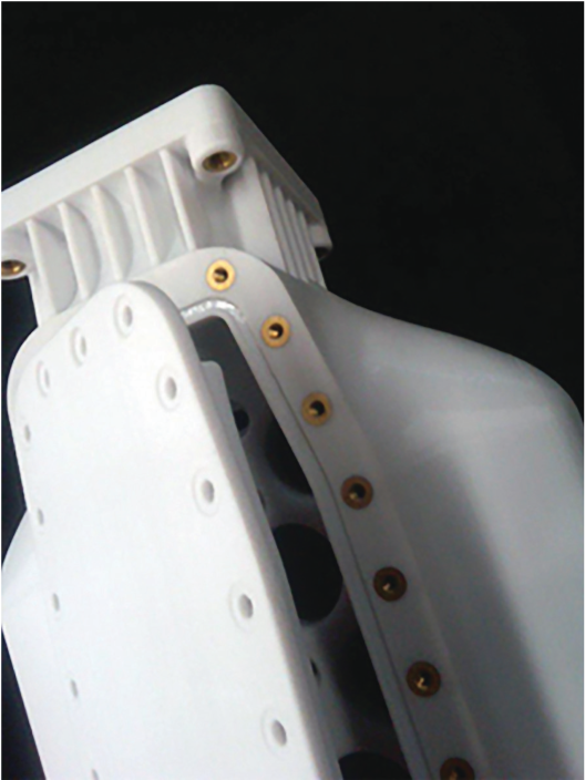
Various types of hardware are commonly used in plastic parts to withstand the torque and load applied when joining parts to create assemblies. Like machined or molded plastics parts, components made with FDM technology can also have hardware inserted into them.
Inserts may be added during an FDM build or in a secondary, post-build operation. This Best Practice covers secondary insertion of hardware with common methods such as adhesive bonding, pressing, and heat setting.
-
Step 1: Tools & Supplies
Adhesive:
• Cyanoacrylate (Loctite® 495)
• Epoxy (Click-Bond CB359)
• Epoxy (Hysol® E-20HP)
Tools:
• Heat stake press (Sonitek Model TS 100)
• Soldering iron (Weller® EC1002)
• Arbor press (Dayton 1-Ton)
• Drill/reamer
Inserts:
• Threaded insert (McMaster-Carr® heat-set inserts for plastic)
• Threaded insert (McMaster-Carr press-fit expansion inserts for plastic)
• Helical insert (McMaster-Carr helical insert)
• Bushing (McMaster-Carr press-fit drill bushing)
• Bearing (McMaster-Carr anged sleeve bearings)
• Locating pin (McMaster-Carr alignment dowels and pins)
• Compression limiting insert (McMaster-Carr press-fit bolt liners)
-
Step 2: Applications
Applications where inserting hardware adds enhanced functionality include:
• Thread reinforcement
- Threaded inserts
• Knurled:

• Expansion:
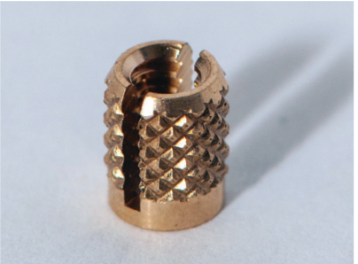
• Helical insert:

• Wear reduction
- Bushing:

- Bearing:

- Wear plate
• Component alignment
- Locating pin:

• Over-torque prevention
- Compression-limiting insert:

-
Step 3: Options
Adhesive bond: This technique requires applying an adhesive to the insert and then mechanically inserting it into the FDM part. This is commonly used when dealing with delicate hardware such as thermally or mechanically sensitive components.
Press fit: This technique requires mechanical insertion of the hardware into the FDM part using an interference fit. This is commonly used when dealing with expansion inserts.
Heat set (metallic inserts only): This is the preferred method for thermally conductive hardware. Using heat to embed hardware into a thermoplastic allows the plastic to conform to the insert and it relieves stress from the interface during insertion.
-
Step 4: FDM Material Considerations
Nylon 12: Best suited for interference style inserts such as compression inserts and helical inserts.
Polycarbonate (PC): Retains surface stress and is therefore best suited for the lowstress or stress-relieving application methods such as adhesive bonding or heat set.

-
Step 5: Adhesive Bond
Step A: Oversize the hole diameter in the CAD model or STL by the required clearance for the insert and the adhesive.
TIP: Use a 0.127 mm (0.005 in) clearance between inserts and FDM components for adhesive unless otherwise specified by the manufacturer or required by design specifications.
Step B: (Optional) Drill the hole to the proper diameter for the selected insert.
Step C: Apply an adhesive, such as Click-BondTM CB359 epoxy, to all contact surfaces of the insert. For details, see the Best Practice: Bonding.
TIP: Ensure chosen adhesive is compatible with substrate and operating temperature.
Step D: Place the insert into the cavity. Make sure the insert seats so that it is parallel to the cavity walls.
TIP: When seating the insert, use a flat surface to press the hardware into the FDM part while maintaining proper insert alignment.
Step E: Remove excess adhesive
Step F: Allow the adhesive to cure per the manufacturer’s instructions.
Step G: Adhesive bond procedure complete.
-
Step 6: Press Fit
Step A: Drill or ream the hole to ensure the proper cylindricity and diameter for the selected insert.
Step B: Place the insert on top of the hole and align it under the arbor press.

Step C: Compress the ram of the arbor press onto the insert and the FDM part until the insert sits flush with the part’s surface.
Step D: Press fit procedure complete.
-
Step 7: Heat Set
Step A: Drill or ream the hole to ensure the proper diameter for the selected insert.
Step B: Pre-heat the soldering iron or heat staking press to a temperature that is approximately 170% of the glass transition temperature (Tg) of the FDM material. For example, use a temperature of 288 °C (550 °F) for polycarbonate parts that have a Tg of 161 °C (322 °F).

Step C: Place the soldering iron or heat stake on the insert. Allow the insert to heat up and then apply light, constant pressure to make the insert sit flush with the part’s surface.
TIP: If the heat set tool does not have temperature controls, simply apply light pressure to the insert with the heated tip and wait for the insert to heat to a temperature that will allow it to be inserted. Minimal pressure is required when using a heated insertion method.
Step D: Heat set procedure complete.