Roller Bearing


Live class link (In Bangladeshi language): https://youtu.be/MrDHA-Dbtpg?si=irL3hUTuLgGn0OTe
Creating a roller bearings drawing in SolidWorks requires multiple thorough processes to correctly describe the bearing's dimensions, characteristics, and requirements. Here's a broad outline for generating such a drawing:
1. Preparing the Drawing: Create a New Drawing, Insert Views.
2. Modeling the Roller Bearing: Create Parts, Assembly.
3. Adding Dimensions and Annotations: Dimensioning, Annotations.
4. Detailing and Section Views: Detail Views, Section Views.
Tips for SolidWorks Drawing:
1. Standard Template: Use standard template for drawing.
Creating a precise and accurate roller bearing design in SolidWorks involves focus to detail, understanding of engineering standards, and expertise with SolidWorks' drawing tools.
-
Step 1: Making Outer ring
Step 1:
Make sketch of the ring.
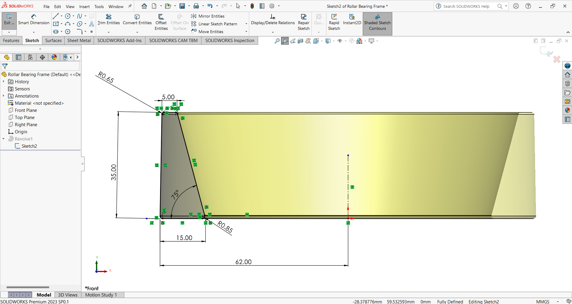
In the picture you will find all measurements.
Step 2:
create solid body from sketch.
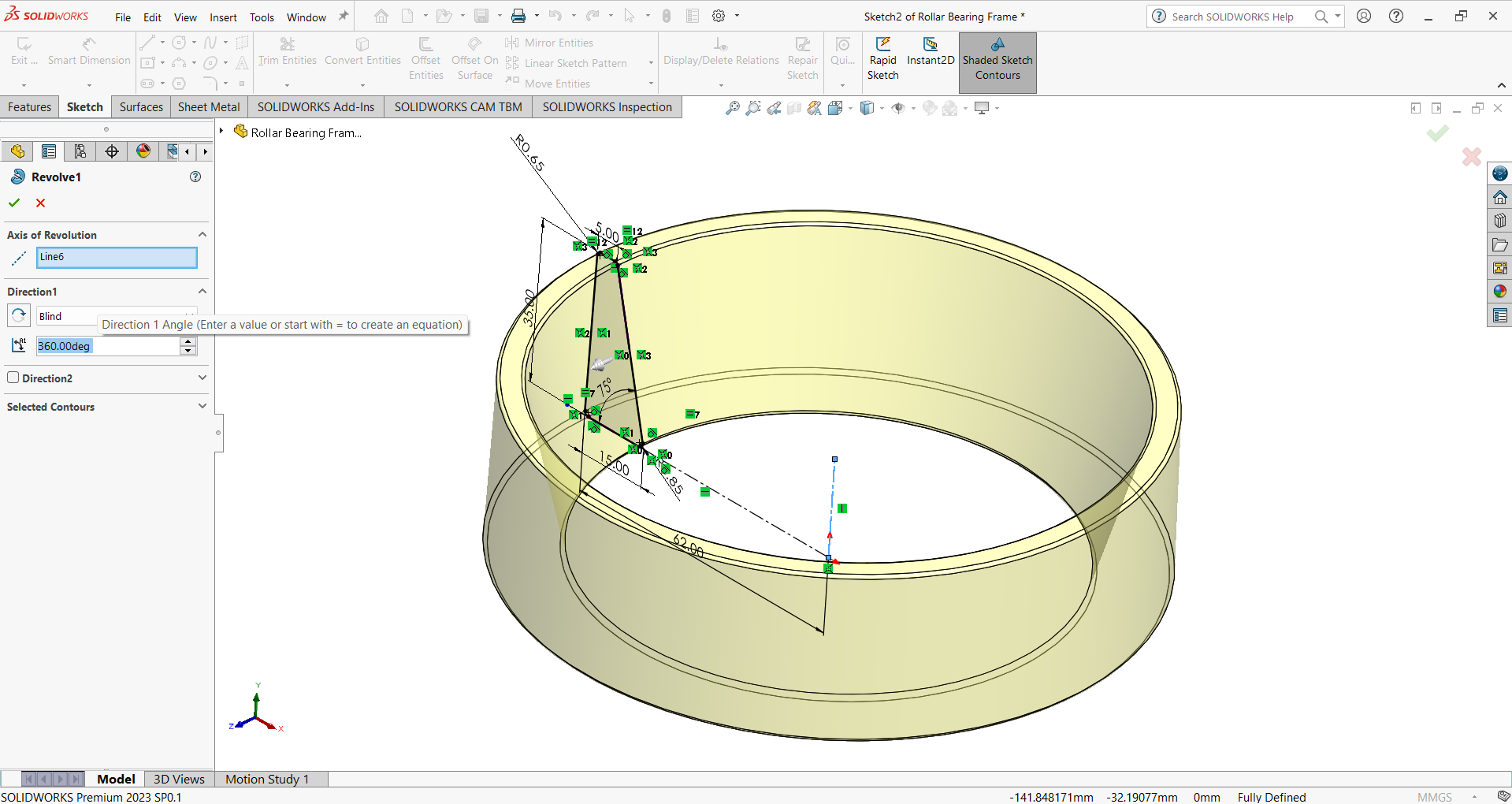
Lets see the sectional view of the solid body.

-
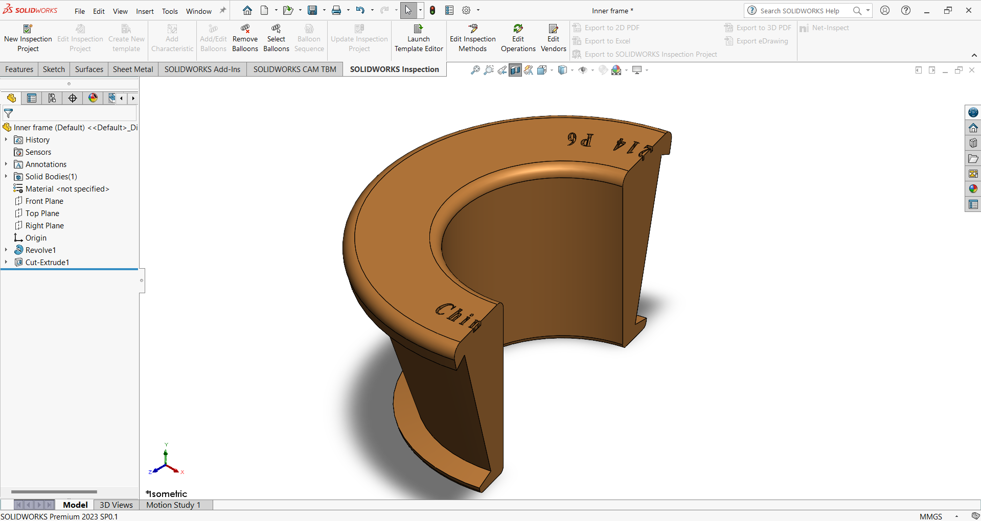
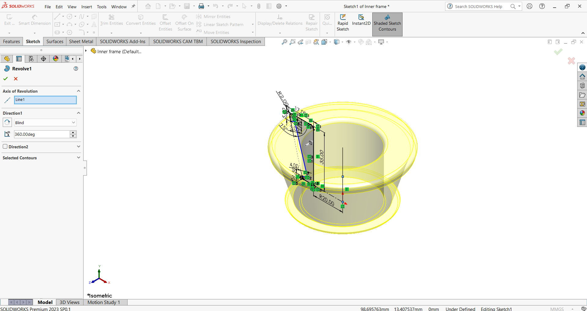
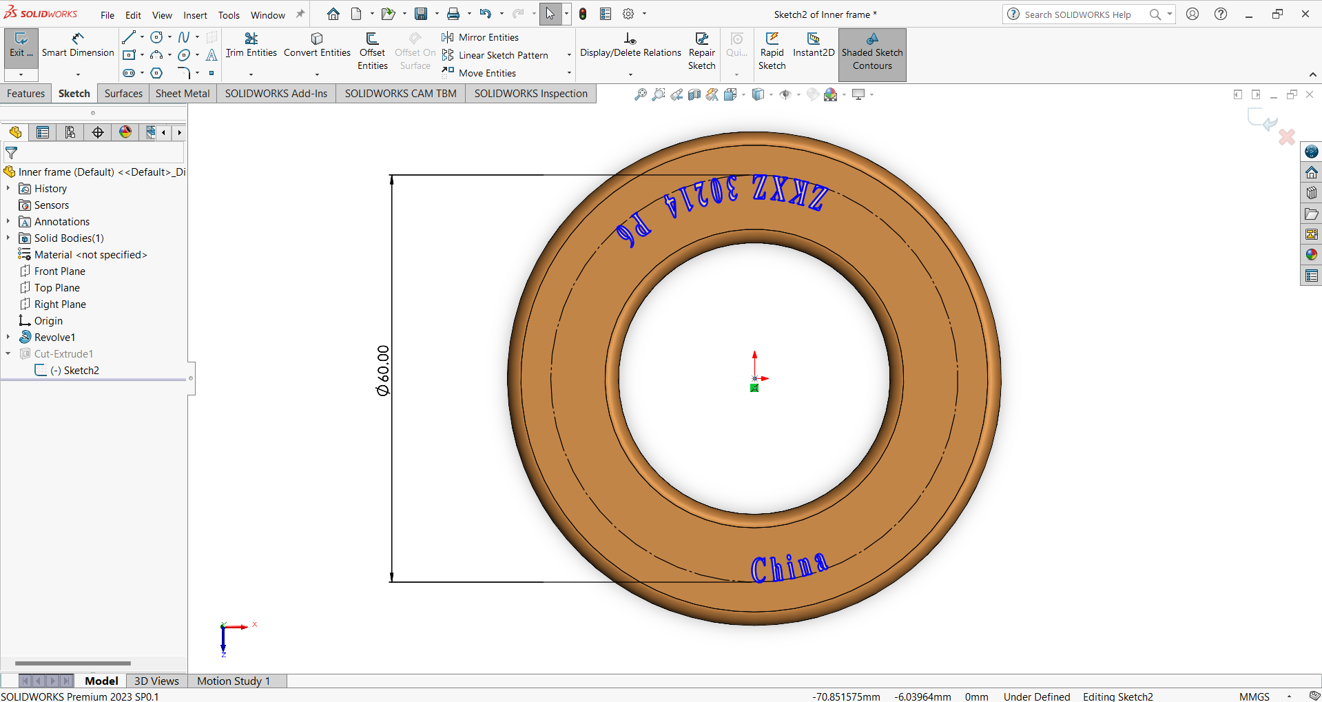
Step 2: Making Inner ring
Step 1:
Make sketch of the ring.

Step 2:
Revolve the sketch.
Step 3:
Sketch model number, origin of manufacturer of bearing.
Step 4:
Extrude cut the sketch.
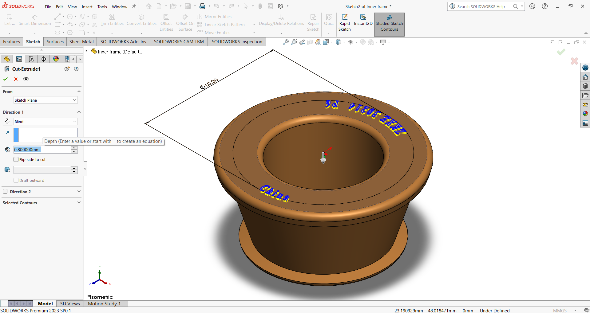
Lets see the sectional view of the solid body.