

SolidWorks - Tutorial 2: Picture Holder


In this tutorial, you will create a picture holder, consisting of a rectangular base with 4 vertical axes on it.
You will get to know some new features, such as the ‘Chamfer’ command. You will also get to know the
‘Assemblies’ command.
-
Step 1: Work plan
This time we will also examine how to shape this design. It has two different parts, which we will design separately. We will then join them together in an assembly.

We will start with the base. We will follow the same steps as we would in the workshop:
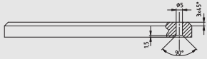
- Use a piece of material with the following dimensions: 150x46x12.
- Chamfer the ribs of the top plane.
- Drill four holes with a diameter of Ø5.
- Counter bore the holes on the bottom plane.
-
Step 2:
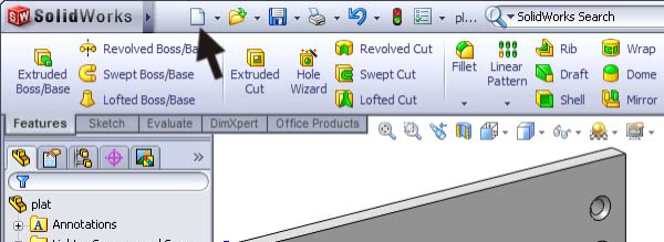
Start SolidWorks and open a new file by clicking on New.

-
Step 3:
Of course, we will start by making a part.
- Click on the ‘Part’ button in the menu first.
- Then click on ‘OK’.

-
Step 4:
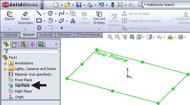
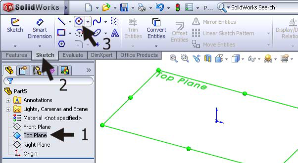
Click on ‘Top Plane’ in the left column of the FeatureManager.
In this plane, we will make a sketch.
-
Step 5:
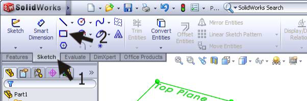
Click on ‘Sketch’ in the CommandManager (which is the menu at the top of the screen) to show the right buttons. Then click on Rectangle to draw a rectangle.
-
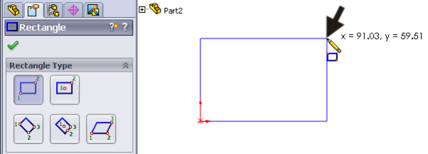
Step 6:
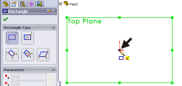
Put the mouse right above the origin, and it will change shape like in the view on the right.
Click once.
-
Step 7:
Move the mouse away from the origin. The dimensions of the rectangle you are drawing will appear at the cursor. The accurate
dimensions are not important yet.
Click again to draw the rectangle.
-
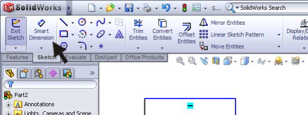
Step 8:
Now, we will determine the accurate dimensions: click on ‘Smart Dimension’ in the CommandManager.
-
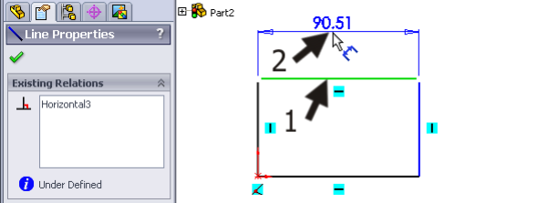
Step 9:
Next, click on the upper horizontal line. Move the cursor up and click at a random position to set the dimension.
-
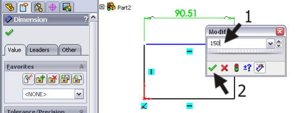
Step 10:
A menu will automatically appear in which you can set the accurate dimension.
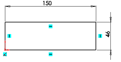
Change the dimension to 150 and click on OK (the green ‘check’ icon).
-
Step 11:
Do the same with the vertical side of the rectangle. Make this dimension 46.
The sketch should now look like the view on the right.
-
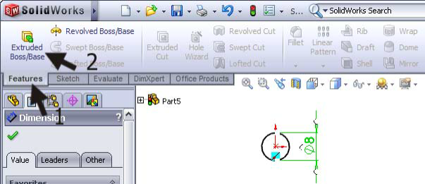
Step 12:
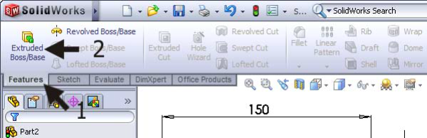
The sketch is now ready, and we will transform it into a rectangular piece of material.
Click on ‘Features’ in the CommandManager and next on ‘Extruded Boss/Base’.
-
Step 13:
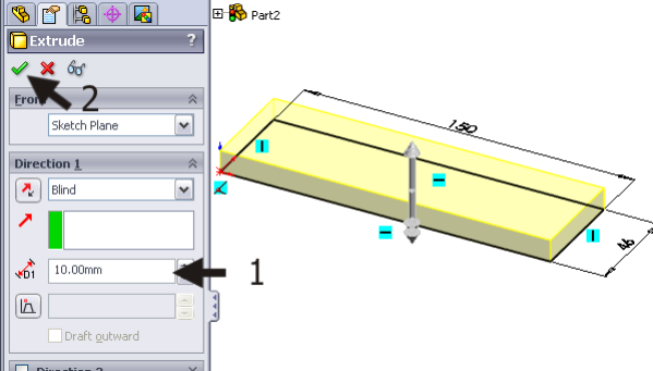
Fill in a height of 12 on the left side of the screen and click on OK.
-
Step 14:
There, the first feature is done already!

-
Step 15:
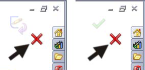
Before we continue, make sure no feature is still active.
Watch the right top corner of your screen. If you see one of the views on the right, then click on the red ‘X’ to close any opened commands.
-
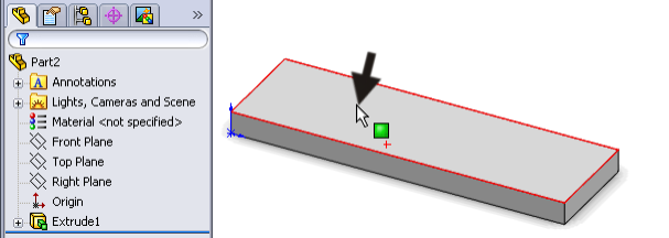
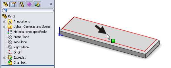
Step 16:
Next, we will create the chamfer on the top plane. To do so, you do not have to make a sketch first.
Click on the top plane of the block to select it.
-
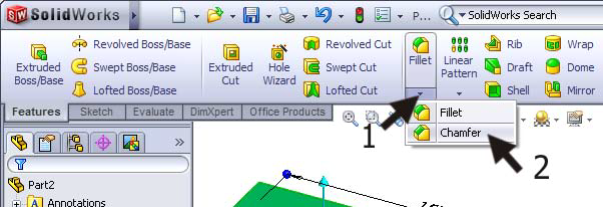
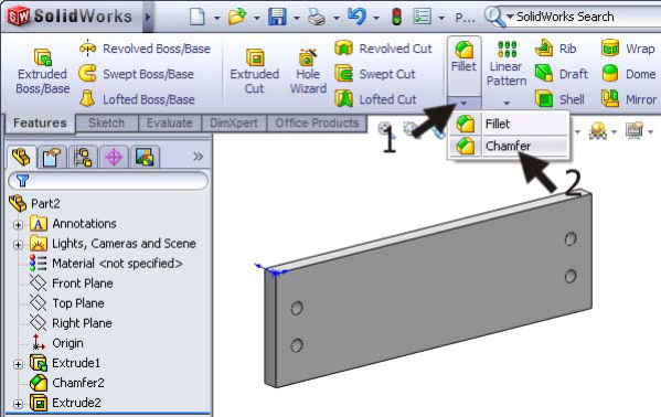
Step 17:
- Click on the arrow directly below the ‘Fillet’ button in the CommandManager to show the roll-down menu.
- Click on ‘Chamfer’.
-
Step 18:
Next, you must check and set a number of items.
- Be sure the options ‘Full preview’ is selected. This will give you a good view of the changes that are going to happen.
- When everything is right, only one ‘Face’ (plane) is selected in the blue field (read the Tip below).
- Set a chamfer of 3mm and 45 deg.
- If everything is set, click on OK.

Tip!
In SolidWorks, you will often see a blue selection field, like in step 17. In this field, you will see the elements of a part on which the command will be executed.
You can remove elements by selecting them and using the <Delete>-button.
You can add elements by selecting them in the part.
In case you have more than one selection field, there will always be only one active field (blue). To activate another one, click inside the desired field.
-
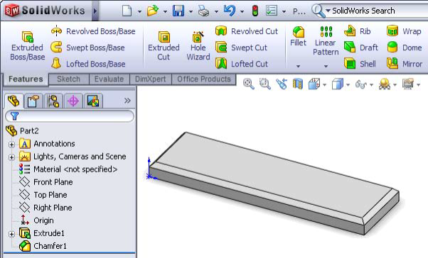
Step 19:
The chamfer is done now.
Tip!
Remember that you can zoom in and out at all times, or you can rotate the model to get just the right view:
- Zooming in and out is done by turning the scroll wheel of the mouse.
- Rotating is done by pushing the scroll wheel of the mouse and moving the mouse.
You can also use the View Orientation button to put your model directly in the right position.
-
Step 20:
We are now going to ‘drill’ the holes.
Select the top plane of the block by clicking on it.
-
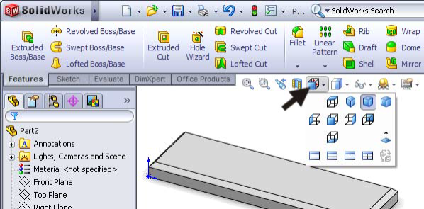
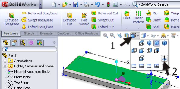
Step 21:
Click on the View Orientation button at the top of the screen and next click on ‘Normal To’.
This command rotates the model and gives you a direct view of the plane you will be working on.
-
Step 22:
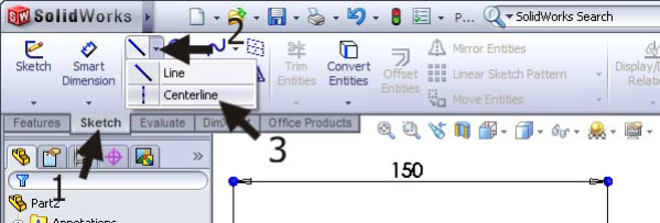
- Click on ‘Sketch’ in the CommandManager.
- Click on the arrow next to ‘Line’.
- Click on Centerline.
Centerlines are construction lines that can help you with the design of a part.
-
Step 23:
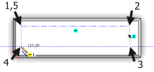
Next, draw a rectangle by using four lines.
- Notice the construction lines will appear and remain. These will help you to draw horizontal and vertical lines and make sure that the fourth corner will exactly fit underneath the first one (look at the drawing on the right). In this way, you will get a closed rectangle.
- Be sure that the corners of the rectangle are not set directly above or on top of another element, such as the edge of a plane.
- After you have drawn the last line you must push the <Esc> button on your keyboard to end the command.
-
Step 24:
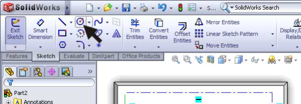
Next, draw the holes. Click on Circle in the CommandManager.
-
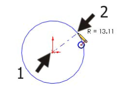
Step 25:
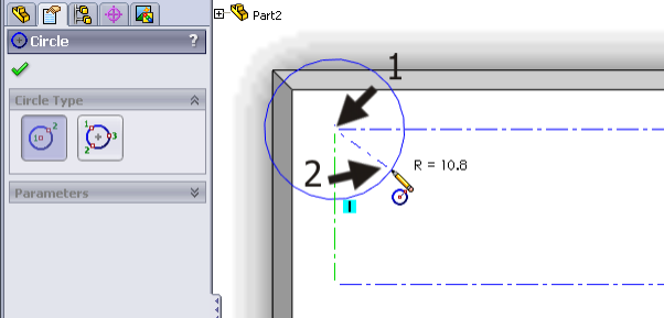
Click at one of the corners of the rectangle, move the mouse, and click again (do not click on another element) to draw the circle. The exact dimension of the circle will be determined later.
-
Step 26:
Use this method to draw a circle on every corner of the rectangle.
After drawing all four circles, push the <Esc> button on your keyboard to end the command.
-
Step 27:
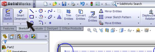
Next, we want to set the dimensions. Click on Smart Dimension.
-
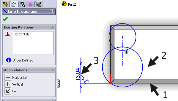
Step 28:
Set the first dimension:
- Click on the lower horizontal line of the model.
- Next, click on the bottom construction line of the rectangle you have just drawn.
- Next, click beside the model to position the dimension.
-
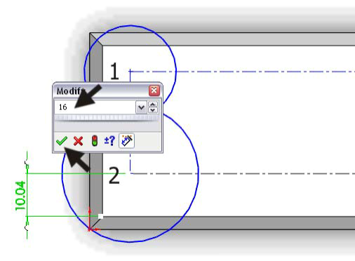
Step 29:
You can fill in a dimension of 16 in the menu that appears and then click on the OK icon.
-
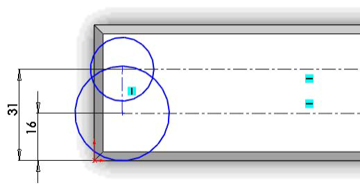
Step 30:
Use this method to set a dimension between the bottom line of the model and the top construction line of the rectangle.
This dimension is set to 31.
-
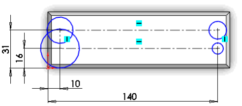
Step 31:
Next, you will set two horizontal dimensions to determine the distance between the left side of the model and the left and right construction line of the rectangle in exactly the same way. Set these dimensions to 10 and 140.
-
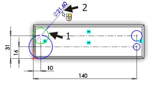
Step 32:
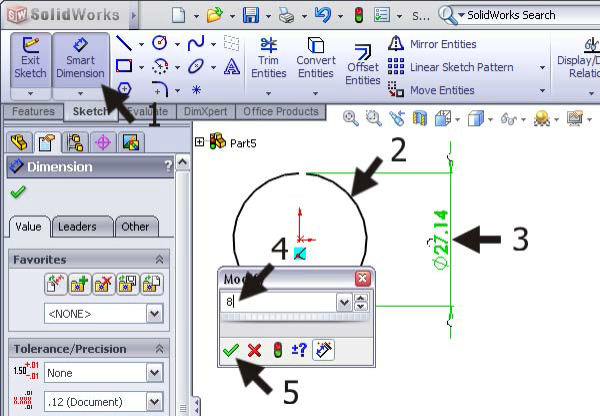
The diameter of the holes must be set now.
Stay in the Smart Dimension command.
Click on a circle and click beside the model to set and position the dimension.
-
Step 33:
Enter a dimension of 5 for the circle and click on the OK icon.
Push the <Escape> button on the keyboard to close the Smart Dimension command.

-
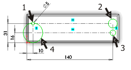
Step 34:
To set the same dimension for all circles, you do the following:
- Click on one of the circles.
2-4 Push and hold the <Ctrl> button on your keyboard.
Next click on the other circles one by one.
5. Release the <Ctrl> button.
If you did this properly, all four circles are now selected (and turned green). If not, click beside the model to unselect everything and try again.
-
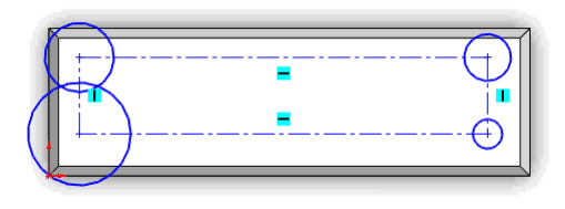
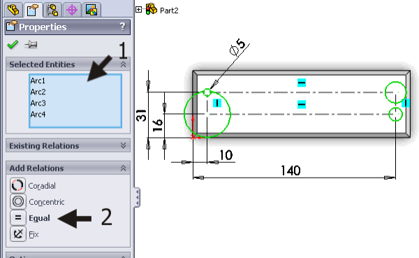
Step 35:
- Check in the left blue field on your screen when you have selected the four circles and nothing else. In the field, ‘Arc’ will be visible four times.
- If so, click on Equal.
You have now added a relation. This relation makes sure that the four holes will always be the same size.
-
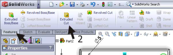
Step 36:
The sketch is finished and we can continue by making the holes.
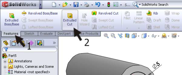
Click on Features in the CommandManager and next on ‘Extruded Cut’.
-
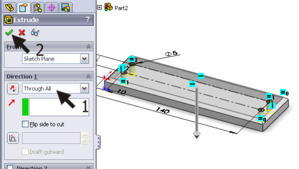
Step 37:
Rotate the model (push the scroll wheel and move your mouse) so you can get a better view.
Chose the depth of the holes ‘Through All’: the holes will go through the complete depth of the material.
Click on OK.
-
Step 38:
Finally, we have to countersink the holes.
Rotate the model so you have a good look at the bottom plane.
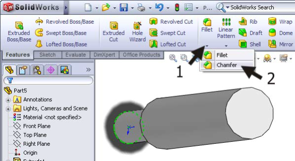
- Click on the arrow underneath the ‘Fillet’ button in the CommandManager.
- Click on ‘Chamfer’.
-
Step 39:
To set the slope, you do the following:
- Select the option ‘Full Preview’, so you can see what is going to happen.
- Set the characteristics of the slopes on 1.5mm and 45 deg.
3-6 Select the edges of the four holes. ONLY select the edges and not the planes. In the blue field, you will read ‘Edge<…>’ four times. If you have selected an incorrect element, click on it in the blue field and push the <Delete> button on your keyboard. Try to select the right element again.
7. When you have selected the right elements, click on OK.

-
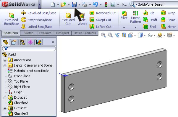
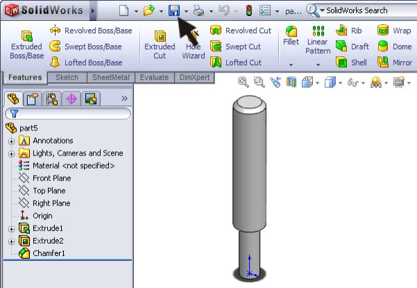
Step 40:
The holes now have a countersink and the first part of this model is ready.
Click on ‘Save’ in the upper menu and save your model as: base.SLDPRT.
-
Step 41: Work plan
Next, we need to make the second part, the axis. Again, we will make a work plan first.
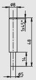
We will create this model in three steps:
- We will take the basic material of Ø8 x 48.
- We will cut a part at the bottom of the axis to Ø5 x 14.
- We will make a sloped edge at the top.
We have seen all these steps before. Therefore, try to make the axis without using the description which follows!
-
Step 42:
Start a new part. Click on ‘New’ in the upper menu and choose ‘Part’.
-
Step 43:
We will use the ‘Top-plane’ to make the first ‘sketch:
- Select the ‘Top-plane’ in the FeatureManager.
- Click on ‘Sketch’ in the CommandManager to reveal the right buttons.
- Click on Circle.
-
Step 44:
Draw a circle. Click on the origin and next move the mouse away from the origin and click again to draw a random circle.
-
Step 45:
Set the dimension with Smart Dimension:
- Click on ‘Smart Dimension’ in the Command-Manager.
- Click on the circle.
- Set the dimension by clicking beside the circle.
- Change the dimension to 8mm in the menu.
- Click on OK.
-
Step 46:
Click on ‘Features’ in the CommandManager and next on ‘Extruded Boss/Base’.
-
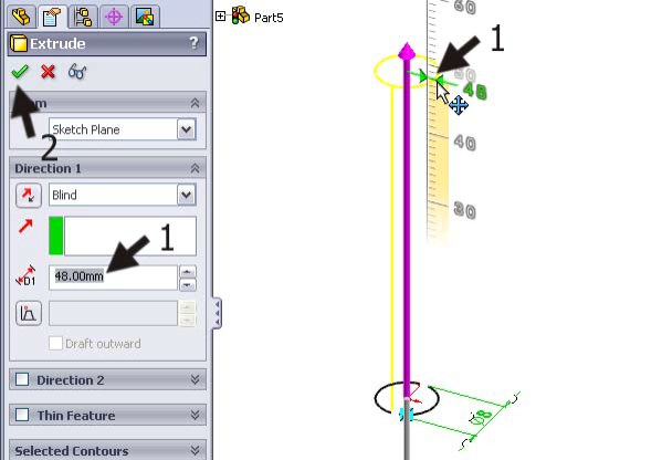
Step 47:
- Drag the arrows in the model to a length of 48mm. Of course, you can also do this by filling in the dimension of 48 in the PropertyManager.
- Click on OK.
-
Step 48:
Rotate the model to get a good view of the bottom of the part (use the scroll wheel of the mouse). Click on this plane to select it (it turns green).

-
Step 49:
Click on ‘Sketch’ in the CommandManager and next on Circle.

-
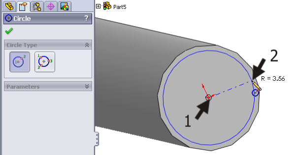
Step 50:
Draw a circle in the selected plane. Click on the origin to get the center of the circle right. Next, move the mouse to draw a circle with a random dimension and click again.
-
Step 51:
Set a dimension of 5 mm for the circle.
-
Step 52:
Click on ‘Features’ in the CommandManager and next on ‘Extruded Cut’.
-
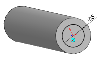
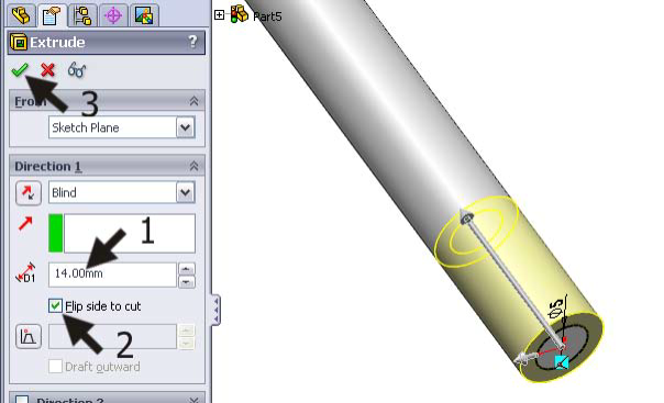
Step 53:
- Set the depth to 14mm.
- Check ‘Flip Side to Cut’ to cut away the outer material.
- Click on OK.
-
Step 54:
The last feature that we have to make is the chamfer at the top of the axis.
Rotate the model so you can get a good view of the top plane.
Click on ‘Chamfer’ in the CommandManager.
-
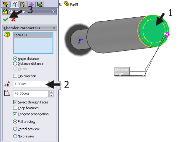
Step 55:
Check and set the following features:
- Select the top plane of the axis.
- Set the distance of the chamfer to 1mm
- Click on OK.
Be sure the option ‘Full preview’ is active so you have a clear view of what is happening.
-
Step 56:
Save the file as pin.SLDPRT.
-
Step 57:
The two parts for the picture holder are ready. We are going to assemble them in an assembly to create the complete product.
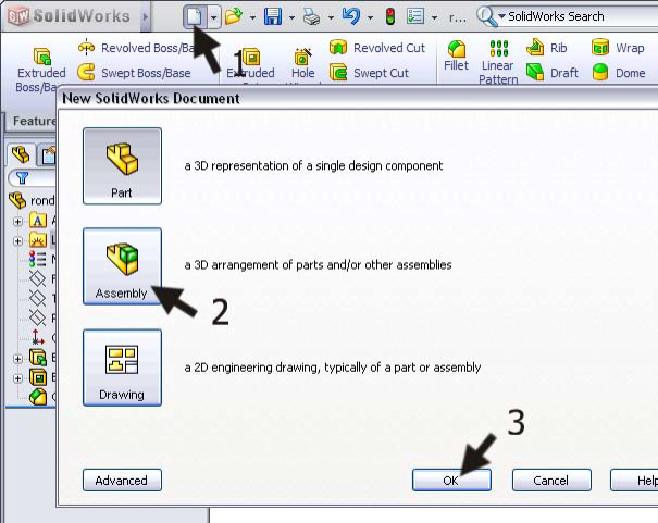
- Click on New in the menu.
- Select ‘Assembly’
- Click on OK.
-
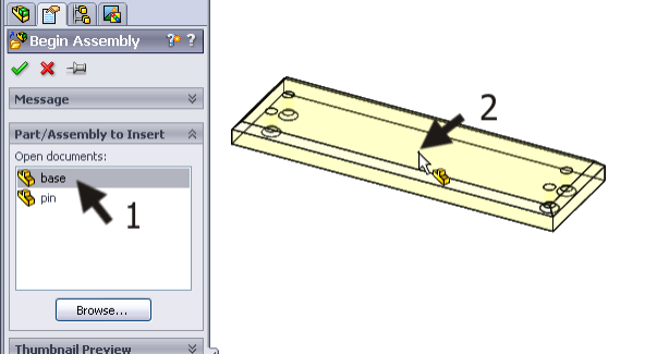
Step 58:
- Click on ‘base’ in the PropertyManager. This is the first part we created.
- Click at a random point in the drawing field.
The part is placed in the assembly.
Pay attention: If this step does not work properly, read the tip that follows.
Tip
In the last step, some commands may not work as described.
- When the left column looks different from the example shown in this step, the ‘Insert Components’ command has not started automatically. When this happens, click on ‘Insert Components’ in the CommandManager.
- When the parts ‘base’ and ‘pin’ are not in the list, you apparently closed these parts. When this happens, click on ‘Browse…’ and find the right files. After doing so, you can put them in the assembly as described.
-
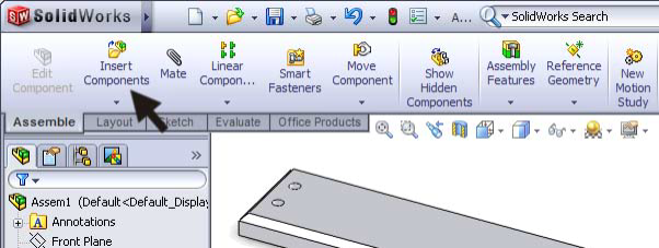
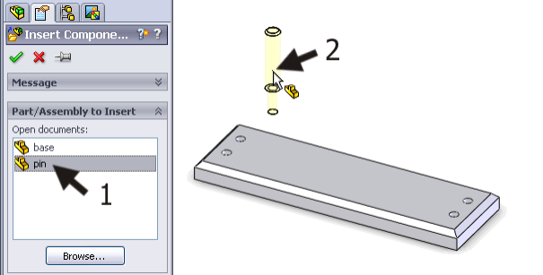
Step 59:
Click on ‘Insert Components’ in the CommandManager to add the first pin.
-
Step 60:
Select ‘pin’ in the menu on the left of the screen and click at a random point in the drawing field to place the part.
If you closed the file pin.SLDPRT, the file will not be on the list (read the last tip again). When this happens, click on ‘Browse…’ and find the file.
-
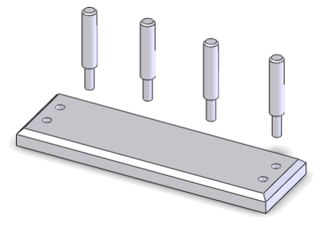
Step 61:
Repeat the last step three times in order to place four pins in the drawing.
All pins are at a random position.
-
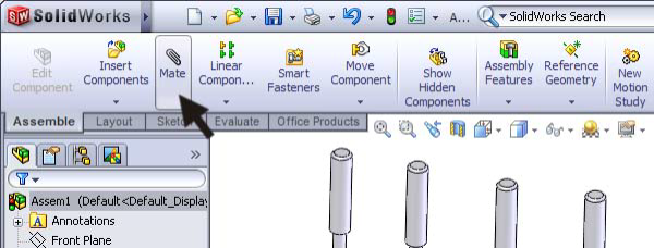
Step 62:
Next, we will place the pins in their accurate position.
Click on ‘Mate’ in the CommandManager.
-
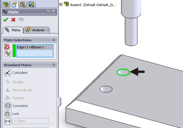
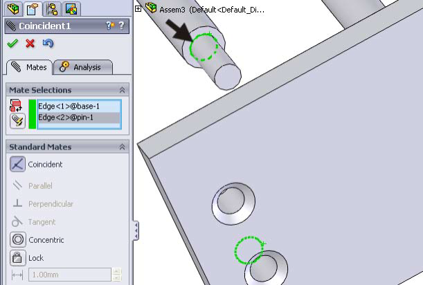
Step 63:
At this point, you will have to select two elements as ‘Mates’. You must do this with the greatest degree of accuracy!
Zoom in on one of the holes in the base part. Select the edge of the hole (Pay attention: it must be an ‘edge’ and not a ‘face’ [=plane]).
In the blue field in the PropertyManager (at the left of your screen) the description: Edge<1>@base-1 will appear.
-
Step 64:
Rotate the model (push the Scroll-wheel, remember?) so you can get a good view of the bottom of the pins. Zoom in when necessary.
Select the edge of the pin as illustrated in the right view. Make sure you do not select a plane.
-
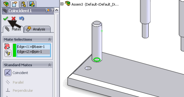
Step 65:
When the two edges have been selected, the pin will be placed into the hole.
When this is done and the result looks good, click on OK.
Tip!
It is very important to select the right elements when making a mate. If you select something other than as described in the previous steps, something completely different will happen or maybe nothing will happen.
When, by accident, the wrong element is selected, think about the description of the blue fields. You can delete a wrong element by clicking on it and pushing the <Delete> button on the keyboard. After that, you can add another element.
-
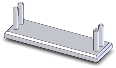
Step 66:
Repeat the last three steps for every pin, so each pin is eventually placed in one of the holes.
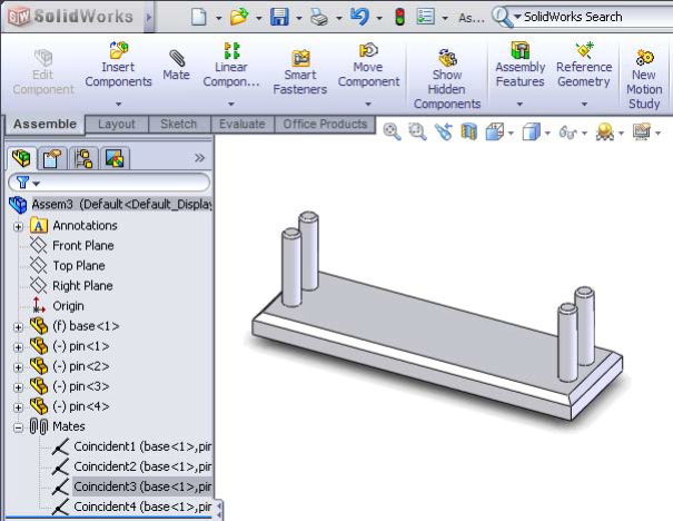
Tip!
Every mate that you create will be visible as in the example below. Do you want to remove a mate? Click on it and push the <Delete> button on the keyboard. You can change a mate by clicking on it with the right mouse button and choosing ‘Edit Feature’.
-
Step 67:
You have just created your first assembly in Solid-
Works! Congratulations.
Save the file as: picture_holder.SLDASM.
-
Step 68: What are the most important things you have learned in this tutorial?
In the part section, you used some new commands:
- You drilled holes.
- You copied the dimension of one hole to other holes using the Equal relation.
- You have made sloped edges with the chamfer feature
After that, you made an assembly:
- You assembled several parts into a complete product.
- You placed the components in their correct positions using the mate command.
You have reached the next level in SolidWorks. In the tutorials that follow, you will use what you know already.