

Tutorial: How to model a variable driven Car Rim Solidworks 2013 and show design intent

Here is the basic tutorial:
If something is unclear just ask.
-
Step 1:
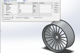
First define (Add) your global variables: Right click on Part tree>Hidden Tree Items>Equations.
You can choose and enter the numbers in mm, inchs, degrees or just blank integers. But try to insert the same numbers for now, so we can avoid confutions later on:)
-
Step 2:
Create a basic rim cross section.
First create the construction lines and add the equations, then create the other elements.
To add an equation just dubble click on a dimension and enter = and select the global variable you want to use in the equation, then add other numbers or operations around this global variable – this way you can avoid the errors.Starting from left, the equations are (I will use this [] for reference dimension, so we won't get lost):
[32,500] =˝HUBDiameter˝/2
[254] =˝Width(J)˝ (don't chose the option from drop down instead enter the text yourself and make sure you include the (J) or else there would be errors)
[80] =100+˝ET˝ (100 is the bottom dimension in this sketch – and it's calculated this way becouse you can avoid errors with negative numbers like this... ET varies around [-50,50])
[261,121] =( "Diameter" / 2 ) / 1.07 (This is just for the ratio to stay the same)
Other dimensions just addapt from the sketch or create your owns – but you have to dimension the same elements in order for the model to work properly.
-
Step 3:
Use revolve feature around the bottom horizontal axis to create a basic rim model.

-
Step 4:
Create a Sketch on the marked surface. Create an construction Circle and for the diameter type in = and choose the global variable ˝BoltCircle˝.
On the highest point of the circle create another small circle for the bolts with diameter 12mm.
-
Step 5:
Use CutExtrude to make a hole through all.

-
Step 6:
Create another sketch on the same surface, with an coincident Circle to the previouse one and a diameter of 25mm.
Use Cut Extrude in both directions (like shown in the picture above) and enable the draft options on both size (Notice that one Draft is outward and the other isn't)
-
Step 7:
Create an Circular Pattern of both Cut Extrudes and in the field ˝Number of Instances˝ enter the global variable = ˝BoltNumber˝. Press enter.

-
Step 8:
Next create a plane on the edge of the rim.

-
Step 9:
Create a sketch on the plane: create an initial vertical axis, convert the upper edge (yellow) and offset the lower one (red) to create two circles.
Add the green line (endpoints on the both circles) and connect the endpoints with two axis. Angle Dimension the first one with an angle of Equation: [1,64] =360/"SpokeNumber"/20 and the second one: [9,35] =360/"SpokeNumber"/3.5.
Next create another axis with angle of [16,36] =360/"SpokeNumber"/2 and then mirror the green line about this axis. At the end, just trim the two circles and add an fillet to the sketch.
-
Step 10:
Create an Circular Pattern and in the field number of instances add the global variable =˝SpokeNumber˝. Press enter.

-
Step 11:
Next create an reinforcement ring like shown above and use the feature revolve to add solid to the sketch.

-
Step 12:
...

-
Step 13:
Use fillets to make the model smother.
Don't use fillets on the parametric driven features yet, becose it will result in long computation times and some errors.
In general, the less fillets u use the faster the computation.
-
Step 14:
Congrats, you're done, now you can explore different options with the model, just dubble-click the global variables on the left (Tree Items) and change its values.
When you're done with costumization, add fillets and materials at your will and post the results:)
