

3D Modeling and Animation of a Spherical Robot in 3DS Max - Part I

The conceptual model creation is described in the following article: IVANOVA, Ioana and Stefka NENOVA, Computer Graphics as a Means of Increasing the Quality of Military Education, Report, Sofia: Yearbook of the Military Academy, 2013, pp. 141-155; http://rnda.armf.bg/wp/wp-content/uploads/2015/03/Binder-1-322.pdf
The development of spherical robots dates back to the 1990s. Their advantage is that they move in all directions, and most often this happens with changes in the center of gravity. Some models use a system of counterweights, which helps to stay still on slopes with an inclination of 33° (Pico Rover). Some are used to study the environment, others - on the lunar surface. They are usually equipped with a high-resolution camera.
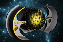
The robot is tentatively named by the author VESPER-006 ("Vesper" means Venus) due to the fact that the planet Venus is a "double" of the Earth due to the close dimensions, although the surfaces of the two planets are completely different. The spherical shape was purposefully chosen to make the robot to resemble the planet it was inspired by. VESPER-006 is thought to be with an innovative design and drive method. It is suitable for research and analysis of the environment regardless of what it is (air, liquid or field). The temperature range is also wide (between -40 and +120°C). The mechanism must be able to reach the point with coordinates (x, y, z) in time space [t].
The design is stylish, simple and facilitates the rotation of the robot around its axis, as well as its movement in space. The dimensions must be such that they can take the weight of the engine and equipment. Apart from an aesthetic purpose, to make the design more interesting, the three side elements (Stands) have been added for their practical function - to stabilize the robot when it is in a static position.
The main steps in the modeling process are as follows:
1. Modeling the side element: first a curve with the desired shape is drawn using Create > Shapes > Line. After that it is extruded by Modifier Panel > Extrude tool. To edit the object, right-click on it and select Convert to Editable Poly. The model can be modified by selecting individual polygons, edges or vertices and using the Extrude and Bevel tools.
2. Clone the side element: by right-clicking on it and selecting Clone.
3. Modeling the spherical body: the outer Geosphere is transformed into a grid by selecting all polygons, Inset and Extrude. The selected polygons should be removed.
-
Step 1: Modeling the side element

-
Step 2: Clone the side element
When the entire element is ready, it should be copied 2 times by right-clicking on it and selecting Clone.
-
Step 3: Modeling the spherical body

