

How to 3D Print in Full Color (Part 1)

This is a series of tutorials to help printer operators who are NOT graphic artists get the absolute most out of their multi-color, multi-material 3D printers, like the Stratasys J750.
We will cover what types of files multi-color printers can accept and how to manipulate colors in Photoshop, Rhino, etc, to get the full gradient texture effects that most color printer users want.
-
Step 1: Levels of Color Printing
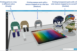
Polyjet printers can print different parts of an assembly in different colors on the same tray.
They can also print imported textures mapped onto flat or curved surfaces of those parts.
They can even print transparent parts with half-transparent textures wrapped completely around them.
But each of those capabilities requires a corresponding increase in the skills and knowledge of the printer operator:

But by mastering all three levels, you will be able to create the most realistic, most useful models for your customers. Let’s get started.
-
Step 2: Definitions
Let’s first define the difference between files coming directly from your CAD system and generic STLs:

The most common engineering CAD systems are SOLIDWORKS, Inventor, CREO, CATIA, and all those programs have a way of exporting STLs.
Now let's define the difference between the two most used full-color, full-texture formats, VRMLs and OBJs:

With those definitions out of the way, some of you might be asking, “Why can’t we just export fully-textured CAD files from our CAD package and print those?” Unfortunately, most mainstream CAD formats don’t retain texture information when exporting their proprietary files:

This seems to be an issue with most mainstream CAD packages (SOLIDWORKS, CREO, Inventor, CATIA) importing into GrabCAD Print, but if we find some exceptions later on, we’ll update this paragraph here.
(Edit 1, 5/2/18: If you are applying colors to CAD bodies and faces only, exporting a VRML from SOLIDWORKS brings those body and face colors into GrabCAD Print for printing on a Stratasys J750/Connex3. Any textures or decals are still lost like in the picture above, but sometimes face color is enough to capture simple intent, like when using colored sunken text or something.
If you are printing with HP style printers, you can export .3MF files from SOLIDWORKS and have those face colors retained.)
Similarly, exporting VRMLs from most CAD packages also seems to strip out texture information too, leaving just base part colors as in the picture above.
(One exception is FEA results from SOLIDWORKS Simulation. If you want to export FEA results as full-colored VRMLs and print them directly with GrabCAD Print, that works perfectly fine. More information here.)
But now let’s upgrade our color 3D printing skills from ‘Simple’ to ‘Medium’ by learning how to re-apply those missing textures onto flat faces for printing.
-
Step 3: Inserting 3D Parts into Photoshop
Since textures don’t export out of most CAD systems but DO export from Photoshop, we’re going to export our shape as an STL from our CAD package, use Photoshop to apply the texture as a layer, and then export a VRML to GrabCAD Print for printing:

Only the “Extended” version of Photoshop can do this, and you can tell if you have the Extended version by opening Photoshop and looking for the “3D” tab at the top:

If you have (or can get access to) Photoshop Extended, your next steps are:
1. Export your 3D shape from your CAD system as an STL ("Save As.... STL")
2. Open a new Photoshop document (it doesn’t matter what size it is).
3. Click on that 3D tab (picture below)
4. Create a "New 3D layer from file" (it also doesn’t matter what size the ‘3D scene’ is) and choose your STL from step 1:

And then you should see your 3D part floating on a grid in Photoshop space:

Besides tools in the lower left to change your 3D orientation (green box above), another useful set of tools is in the top right, to reset yourself to one of the standard Top, Front or Right views (very useful to make sure your texture is parallel to one of the model’s flat faces):

Finally, one last set of tools to have visible is the Layers toolbar, since all Photoshop commands only affect the active layer. What you should see at the start is 2 layers (the background and your 3D part), and what we will see after the next set of steps is 3 layers (after adding your texture image as a layer on top):

You can tell which layer is the 3D part by the small cube in the layer icon, pointed to by the blue arrow above.
Now that we've actually gotten our 3D shape into Photoshop, next we're going to apply our image as a texture.
-
Step 4: Inserting and Merging Your Image Texture Layer
The command to place the image is called “File…Place Embedded”.
So you are going to:
- Start the "Place Embedded" command.
- Drag and resize your image to make it fit how you want to.
- Hit the gray checkmark to finish placing your image as a layer (check only shows once Place Embedded command has been started):

Now you should have 3 layers as shown in the previous step (Background layer, your 3D part layer, the texture layer). What you should see if you rotate the 3D part is that the texture does not stay flat, since it is not yet connected to your 3D part yet:

Note the three layers in the bottom right. Delete your background layer (it’s not needed), make sure your model is lined up with the texture by carefully using your standard views and your zoom tools, and then right click on your top-most, texture image layer and choose “Merge Down.” It should look like this:

You should now see only one layer, with a texture that stays attached to your 3D part no matter how you rotate it:


Next we’ll see how to get that 3D part into your print preparation software.
-
Step 5: Exporting Your Textured VRML to GrabCAD Print
Right click on your single remaining 3D layer and choose the “Export 3D Layer” command:

In this command, make sure to change the file type to “VRML” (red arrow 1) and change the Texture Format to “JPEG” or “BMP.”

The result of this command will be a VRML file (.wrl) saved on your computer, and also a texture JPEG file (or BMP) saved right next to it. You need to keep these two files in the same folder, or the texture won’t be found while you’re reading the VRML into GrabCAD Print:

But after all that, when you import that VRML file into a PolyJet tray inside of GrabCAD Print, you’ll see your texture on your part, ready for 3D printing:

You could print that part right now on a J750 and the color texture should print as shown.
Next, we'll see what to do if your image didn't merge down correctly and how to make things bit more complicated.
-
Step 6: How to Make Things More Complicated
Some of you, when you hit the “Merge Down” command in Photoshop, may have seen your texture get very blurry and fragmented:

This is because the underlying method of how textures map onto the faces of your model was not smooth and correct. This is called “UV mapping” and if you look at the UV maps of each result, you can see why one may have worked better than the other:

In the second part of this tutorial series, we’ll look at how to adjust UV mapping to solve this problem, how to use Rhino and other tools to better apply textures (even to curved bodies) and how increase your color 3D printing skills even more!
-
Step 7: Finished Result
This image is here to ensure a good thumbnail on the tutorial, and to show where we've come from and where we're going next time!

To learn even more about the powerful, office-friendly full color printers you can use to create models like this, right in your own office, check out Stratasys' new J55 series of machines here.
