

How to 3D Print Jigs & Fixtures, Part 2: Designing for Print


This is the second part of a four-part tutorial series on how to optimize your manufacturing jigs & fixtures for 3D printing. Today, we'll go over what to do in each design pass as you're optimizing your part, including specific steps to do in your CAD package, your print-preparation tool, and if you're bold, your FEA package.
Later installments of this series will deal with FDM material selection and post-processing for jigs & fixtures.
-
Step 1: Now what?
In part 1 of this series, we discussed how to choose which jigs or fixtures from your shop floor to redesign first.
Now we will go over how to actually redesign your traditionally-manufactured tools for 3D Printing.
There will be many tips given in this tutorial, but the over-arching principle is: “Go from BIG to SMALL”. That means our first few design passes will make large, far-reaching changes to the nature of our jig or fixture, and later ones will make smaller and smaller changes to optimize targeted areas.
Let’s begin.
-
Step 2: First, Identify Critical Surfaces
Most jigs and fixtures have just a few key surfaces that touch your workpiece, and everything else can be considered up for redesign.
For example, in the sample fixture below, only 6 surfaces are truly critical to its operation:
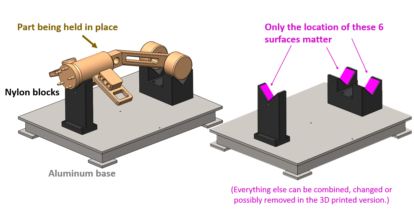
Everything else, the nylon blocks, the aluminum base, the bolts holding them together, all can be altered or removed as long as the redesigned fixture has those 6 purple faces in the same place as before.
So at this stage, each of these possible redesigns would work equally well:

We’ll consider strength and feasibility of those shapes a few steps later, but the point right now is to embrace the design freedom that 3D printing offers. As long as those six purple faces are in the same place, the rest of that fixture can look like almost anything and still do its job. So don’t limit yourself here – 3D printing can handle nearly any level of complexity.
Pro tip: offset those faces!
We're going to be making a lot of changes to your jig or fixture in subsequent design passes. One way to set yourself up for success is to make a copy of your critical faces in 3D space in your CAD system right now, before any changes. This will give you something to compare your redesigns against later.
Assuming you're working in SOLIDWORKS, and assuming your jig or fixture is an assembly, the procedure would go like this:
1. Make a new, in-context part to hold the faces inside your assembly:


2. Edit that part and select your critical faces:

3. Choose the command "Insert...Surface...Offset" and choose an Offset of "0" (to make a copy of those faces right where they are):

(Yeah I know the command was invoked as "Offset Surface" but displays as "Copy Surface". That's just a SOLIDWORKS thing.)
4. In that new part file, you now have a set of your critical surfaces floating in space:

Those purple surfaces will be what we compare our later steps to, to make sure we didn't move any critical faces during the redesign.
Now let's do our first, and largest, design pass to change in our jig or fixture for 3D printing: consolidating parts.
-
Step 3: Next, Consolidate Parts
After identifying your critical surfaces, the biggest change you will make to your Jig or Fixture is to consolidate and integrate parts and sub-assemblies.
Consider this tool-arm end-effector from one of our customers (Genesis) and how radically it changed for 3D printing:

Not exactly a jig or fixture, but the principles are the same. In the old design, there used to be one sub-assembly to supply structure to the tool (the metal frame), and another whole sub-assembly to bring in the air lines that would eventually create a vacuum to pick up the work piece at the end of the robot arm (seen in clear on the right).
The genius of the redesign was the customer realizing they could 3D print the cavities for the air lines to run INSIDE the structural arm, integrating the two sub-assemblies, and if they used the right FDM material (Ultem 9085), the arm would still be strong enough to do its job. (And be about 90% lighter!)
Big complexity savings, big weight savings, and that's what we're going for.
Sometimes it's hard to decide what parts to combine and what to leave alone, or where to draw the lines separating two different sub-assemblies. So here we're going to rely on two time-tested and over-arching design principles, namely:
- Designs tend to fail at the interfaces, and
- Use sub-assemblies to isolate risk.
Both of these are from Donald Reinersten's great book, Managing the Design Factory, (which every product design engineer should totally read, even though it's old).
Let's look at the first principle: Designs tend to fail at the interfaces.
If you had to guess where the below design would most likely fail, where would you choose?

And before you say, "That's just a result of the force diagram!" consider this scenario:

In your real-world experience, where do products fail MOST OFTEN?
Traditionally manufactured jigs and fixtures were made from off-the-shelf parts cut and attached to get the job done. There are a lot of interfaces where things could get loose, get mis-aligned, separate and fail. Consolidating parts with 3D printing removes those interfaces.
But on the OTHER side of the coin, we have the principle: Use sub-assemblies to isolate risk.
For example, if you were designing a console where there was a reasonable risk your customer would want to change the size/position of your buttons halfway through, then which would be the safer design:

(Hat tip to GrabCAD Community member Onur Can Acayir, for his very detailed dashboard model used above.)
So if your jig or fixture has a locating pin that breaks all the time, and if you just can't make that area stronger somehow, consider making the pin a replaceable sub-assembly, so if it breaks, you don't have to reprint the ENTIRE tool from scratch.
Those are the two philosophies providing tension when deciding how to consolidate parts during a redesign: fewer parts means fewer interfaces to keep track of and to fail, but a more segmented design allows for more flexibility if something does fail. Just like all design, there's no always-right answer, but how you choose to tackle that question defines your style as an engineer.
HOWEVER, in general, for 3D printing redesigns, your bias should be towards consolidating many parts into one, since we can print a single custom shape to accomplish what many off-the-shelf parts can't.
In our super-simplified example, look at how many parts (and part numbers and tracking cost) I could possibly remove from our shop floor:

So that's the biggest iteration you'll do when redesigning your jigs & fixtures for 3D printing. Take a lot of time here – this is where a lot of the weight savings comes in. After you've consolidated as much as you can, next you should look at designing for your human operator.
-
Step 4: Now, Design for Ergonomics
This is a huge design iteration everyone forgets to do early. People usually leave ergonomics for later design passes, when it's too late to change anything big.
But because of the freedom we have with 3D printing, especially making contoured or blended surfaces and handles, you should do it now, as your second big design pass.
There are entire books and courses written about the principles of ergonomic product design, but we'll boil them all down into two big ideas here:
- Watch your Center-of-Gravity (CG) compared to your lifting point and,
- Size your handle diameter to be comfortable for your target user
For any hand-held device (and we're assuming most of your jigs and fixtures will need to be moved or re-positioned by human hands) the ease of lifting, holding and moving it varies inversely with the distance from CG to grip:

There are a thousand ways to prove this principle, but the easiest is: take any baseball bat, hockey stick or axe you have lying around your office and hold it out from your body, gripping it in the middle near its CG.
Pretty easy to hold for a while, right?
Now grip it three-fourths of the way towards one end and hold it there, out away from your body for a while. Feel the uncomfortable torque building? Now grip it at the very end, farthest from its CG, so the CG has a long moment arm you have to fight against every second. Really not fun, right?
(Stratasys/GrabCAD is not responsible for any pulled muscles or baseball bat injuries resulting from these tutorials.)
Most tool designers just place their handles at either end when they've run out of time for designing their tool, but now you know better, don't you:

Pro tip: Don't guess at your Center of Gravity!
Most all modern CAD tools have a way for you to calculate the CG of your part on screen. SOLIDWORKS calls it Mass Properties:

This helps you place your handle/end pro tip.
Ergonomics part 2: Size your handle diameter for your user.
Just as the distance between your CG and your handle affects ergonomics, you have to size your handle to match the diameter of your operator's grip. In general, too big grips are better than too small:

(That image from this helpful guide to handle design.)
Typically a diameter of 3-4 cm. (around 1-2 in.) will work best, but the good news here is- you've got a 3D printer! Print out 4-5 handle designs of different sizes and shapes and have the intended operators actually choose which one they want to use on the final piece!
If I was designing my sample tool for real, I'd probably test out a comfort bulge in the middle based on these principles:

Okay, after you've done a thorough design pass to make sure the ergonomics of your tool are comfortable to your end users, next we're going to look at strength.
-
Step 5: Designing for Strength 1 (Orientation and FEA)
Material is a large determiner of printed part strength, but we're going to spend all of part 3 of this series talking about choosing the best FDM material for your jig or fixture. So for these next 2 sections, I'll only talk about ideas that affect strength no matter WHAT material you print in.
The biggest single decision you can make to affect FDM part strength is orientation. If you zoom in on FDM printing, it usually looks something like this:

Depending on the type of printer you use and the speed/feed settings, your beads may look a little more or less elliptical, but that's a general idea: beads get laid down in the X-Y plane, usually in alternating directions, and layers get added in the Z.
For strength, this means that forces in the X and Y directions have to try and stretch the solidified beads and overcome the original material strength in tension (which is hard), but forces in the Z direction simply have to pull the layers apart (which is a lot easier).
Therefore, your part is:

How much of a difference is there between strength in the XY and in the Z? It's hard to say, but some simple tests we've done show it could be up to 50%.
You can even see it with your bare eyes, if you print a few test dog-bones standing up on your tray and laying flat. The ones standing up fail by their layers coming cleanly apart (at a lower stress) and the ones laying down fail by their beads being torn and snapped (which takes a lot more force to get the cup-and-cone formation):

So how would you know which way to orient your parts on your tray? You could eyeball it, but there already exists a tool to tell us the stress directions inside CAD shapes, and it's called Finite Element Analysis (FEA).
There are many other tutorials about FEA use, but for 3D printing, all you have to do is restrain your part as it would be held in real life, put forces on it in the same direction as it would see in operation, and look for the largest principal (directional) stress:

Most FEA users look at the Von Mises stress, which is pretty. But for printing, you have to look at those directional vectors and make sure your largest operational stress will be pulling ALONG your layers (XY) and not pulling your layers APART (Z).
In this case, it's obvious that the strongest direction would be to lay the dogbones down flat on my tray to print (XY) and if you test it, that's exactly what happens.
No matter how complex your part, or its restraints, or its loading is, take comfort in the fact that there will always be only one direction of largest principal stress, and that's all you're trying to find out with FEA:

So find that direction of largest stress and orient your part to make sure it's along your XY tray.
Pro-tip: Never trust the MAGNITUDE of FEA calculations on 3D printed parts!
FEA can be a great tool to tell you the direction of largest principal stress, but never trust a computer to tell you the size of that stress, or when your printed part will break.
Always remember the difference between FEA and real life:

Right now, there's no established correlation between the amount of stress FEA calculates and the amount of stress felt by discrete beads of FDM plastic touching each other at a thousand imperfect interfaces. The printed part will always be weaker than FEA predicts, we just don't know how much weaker. But the location and direction of stress will generally be correct.
So use FEA to tell you WHERE your printed tool will break, but never WHEN.
After you've taken care of orientation, the next biggest thing you can do to make sure your jig or fixture stands up to daily use is to add extra infill where needed.
-
Step 6: Designing for Strength 2 (Controlling Infill)
After choosing the best material and orientation, the next largest thing you can do to make sure your jig or fixture lasts for after cycle and cycle on the shop floor is controlling how the printer puts down infill.
GrabCAD Print (and most other print-preparation tools) contain a few, predefined, infill modes:

You can see how each mode makes the infill more dense, resulting in stronger (and heavier) parts. You can also see how each mode affects the entire part at once.
There's no easy way (in common print preparation tools at least) to dictate that THIS SPECIFIC AREA of your jig get a stronger infill or that THIS FACE of your fixture have more contours behind it than the others to prevent wear.
This is because most print preparation tools import only STL files, which are hundreds or thousands of triangles, so that clean faces and internal areas don't really exist in them:

To combat this STL-only bias and lack of control, GrabCAD Print is beta-testing a new piece of software called (appropriately enough) GrabCAD Jigs & Fixtures.
Jigs and Fixtures is a new app that runs right inside of GrabCAD Print, takes in CAD files DIRECTLY, and allows users to choose any CAD body or face to apply more infill or contours to, with just a simple slider:


This ability to add extra infill and contours by CAD body or face is letting our beta customers do some unique things with their jigs & fixtures, making them strong and tough right where they need them, and light and rigid everywhere else.
Since we're selecting CAD faces directly, we can also do unique things such as resizing holes to accept a wide library of standard inserts, without having to go back into CAD:

But again, GrabCAD Jigs and Fixtures is just in beta right now. If you have one of the supported Stratasys printers (F370, Fortus 380, Fortus 450, Fortus 900), print a lot of manufacturing aids and want to control your infill at a better level than before, go here to sign up, and hopefully we'll see you in the next round of the beta!
For everyone else, let's move on to the last and smaller design iteration you'll do for your jig or fixture: little Design For Additive Manufacturing (DFAM) touches.
-
Step 7: Little DFAM touches
There have been a lot of tutorials about how to prepare parts for FDM manufacture, and I'm not going to go over all of them again here. (Even though a few are really useful.)
I'll just point out that all those small changes you do to make your parts self supporting or a little bit easier to clean should be done now, AFTER you've consolidated as many parts and sub-assemblies as you can, AFTER you've designed for ergonomics, AFTER you've chosen your best build orientation and decided which areas of infill you're going to strengthen in your print preparation tool.
For example, look at all these small changes you can do to make your internal bosses self-supporting and remove 25% of your build time:

You can't do ANY of those until you've chosen your best build orientation, which depends on the FEA analysis of your tool, which depends on how many sub-assemblies you've consolidated in your more efficient design!
So definitely add fillets to corners, change your overhang angles to be less than 45 degrees so they can support themselves, reinforce holes you're going to drill later, but just do it AFTER all the other changes I've mentioned. That's all I'm saying.
-
Step 8: Final thoughts
Okay, so in this tutorial we've covered six design iterations you should go through, at a minimum, to redesign traditional jigs & fixtures for 3D printing.
You may even have to go through more than one cycle each iteration, like doing two or three passes to combine sub-assemblies or make sure your ergonomics are correct, but that's the general order to follow, if you want to get the most benefit from 3D printing your jigs & fixtures:

And that may look like a simple example, and it is, for teaching purposes. But in the real world, large automakers are using the exact same principles to make very efficient and optimized tools, like this tail light positioning fixture:

That's a case study we did, and if you want more information about that or other validated successes, email me at shuvom@grabcad.com. Click here to see how 3D printing can save you time, costs, and improve safety.
In part 3, we'll talk about how to select the best possible MATERIAL for your 3D printed jig or fixture.
