

[VIDEO] Beam Calculation Simulation Tutorial 1/2-Finite Element Analysis with Weight-Mixed Mesh -Solidworks

WATCH THE VIDEO LOW, GET DOWN THE SCROLL BAR
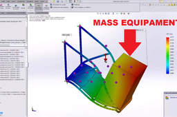
In this video I will teach how to calculate a metal structure considering a weight of an equipment in a certain region of the structure - STRESS ANALYSIS - FINITE ELEMENT ANALYSIS SOLIDWORKS SIMULATION TUTORIAL
================= =================
DO NOT CLICK HERE: http://bit.ly/projetos_infinity
================= =================
join our youtube community:
https://www.youtube.com/channel/UCF2k47g7uAo0lM-kA13V6jQ?sub_confirmation=1
Here's how to take a solidworks whatsapp course with me:
https://www.youtube.com/watch?v=RQgoTn96wAw&t=174s
-
Step 1:
-
Step 2:
For this we will have to create a new density for the equipment, so that it stays with the mass that we want, that in the case will be of 500 kilograms
infinity projetos brasil
We will measure the equipment (width, length and height), to calculate the density
Having the density found, in this case the value of 251 kg per meter³, we will now create this new material with the new density in solidworks
To do this, right-click on some material, then click copy, then right-click a region without the folders again, and click new library, give this library a name and click ok , Make this new library, right click on it and click on new category, give it a name, and then right click on that category and paste, edit the name of the new material and also the density that In this case it will be 251
After changing the material of the equipment, we see that it already has the mass we want, which in this case is 500kg
Now let's visualize the center of gravity, see that the center of gravity changes when we remove the equipment (chiller of 500kg), and when we de-suppress the center of gravity changes again
We will now create a new simulation using as a principle the concept of mixed meshes, ie fabrics with structural designs and with solids, to start, we exclude pulp from list of cuts, we see that all components are already with their due materials, which in the case Are: aluminum plaque 1060, 1020 steel frame and chiller with the material created. If your pieces are not with material, you must choose the material of each piece. For this simulation, the chiller does not want to study its behavior so that it deforms, we will use it only to have its mass in the desired region, so we have to treat it as hard, as I change it by right-clicking Mouse over it and click on make it hard
Now let's include gravity, which will consider everything in the drawing, including the 500kg chiller, see that gravity is applied in the center of gravity
Now we are going to join the structural components with the solid components, this is very important to work with the mixed meshes, because it will show where one will support the other, to do this right click on components contacts and then click on set of Contacts, change the type to instead of without penetration to join, click on beams, then select all the beams that will hold in our case the plaque plaque and click ok, repeat the process to join the chiller with plaque plaque
Now create the mesh and see that the mesh of the chiller will be orange, this occurs because we treat it as rigid, ie it will not be analyzed in the result, we will only use its mass
Now click run, to calculate the structure
In this first result, it presents the tension only in the solid bodies, does not show the tension in the beams
See that the maximum voltage was 7.3 exponential 6 newton per square meter, that is, it did not exceed the flow limit that in the case of the plaque is 2.7 exponential 7 newton per square meter, ie there will be no plastic deformation , Is a deformation that the part returns to when removing the force
We will see how to know the flow limit of each material, when we edit the material the same has the flow limit, for AISI 1020 steel we have 3.5 exponential 8 newtons per square meter, already the structural steel A36 that is normally used and metalon Has a flow limit of 2.5 exponential 8 newtons per square meter, and in the case the aluminum comom 1060 has 2.7 exponential 7 newtons per square meter
The second shows how much everything will move, not only considering plastic displacement, but all buckling by weight even if it is in the elastic zone
The third graph will show how much there was plastic deformation, see that the number is extremely low, ie there was no plastic deformation
Now let's insert the fourth graph, which will serve to analyze the tension in the beams, to do this right click on result, then click on tension, and in definition change to beams
See that the maximum stress in the beams was 8.8 exponential 6 newtons per square meter nearly 40 times lower than the 1020 steel flow limit which is 3.5 exponential 6 newtons per square meter, ie is suitable and not Deform
Now let's do the same process to analyze the safety factor, see what the lowest value was 3.7 times, or the point that has less safety is 3.7 times more resistant than necessary
